
Installation Guide Owner's manual
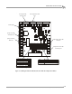
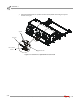
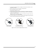

Table Of Contents
- Cover
- Copyright
- Table of Contents
- Warnings
- 1 - Specifications and Operating Requirements
- 2 - Stationary Dyno Installation
- 3 - 4WD Dyno Installation
- Unpacking and Inspecting the Dyno
- Track Assembly
- Dyno Installation
- Cable Routing
- Identifying the Cables
- Routing the Cables—Without the Eddy Current Brakes
- Wiring the Breakout Board—Without the Eddy Current Brakes
- Routing the Cables—With One Eddy Current Brake
- Wiring the Breakout Board—With One Eddy Current Brake
- Routing the Cables—With Two Eddy Current Brakes
- Wiring the Advanced Breakout Board—With Two Eddy Current Brakes
- Hydraulic Movement Installation
- Air Can Sleeve
- 4WD Dyno Movement Test
- Bridge Installation—Stationary Dyno
- Bridge Installation—4WD Dyno
- Deck Installation
- Logo Panel Installation
- 4 - Eddy Current Brake Installation
- Eddy Current Brake Installation
- Before Installing the Eddy Current Brake: Verify Optimal Brake Cooling
- Before Installing the Eddy Current Brake: Verify Mounting Holes
- Unpacking the Eddy Current Brake
- Installing the Temperature Sensor
- Installing the Bearing, Splined Shaft, and Driveline Assembly
- Installing the Eddy Current Brake
- Installing the Load Cell
- Installing the Front and Rear Brake Covers and Theta Controller
- Torque Module Installation
- Load Cell Calibration
- Eddy Current Brake Installation
- 5 - Side Deck Assembly Installation
- 6 - Basic Dyno Operation
- A - Red Head Anchor Installation
- B - Power Requirements and Installation
- C - Stationary Dyno Upgrade
- D - Bridge Extension Assembly
- E - Interface Roller Assembly Installation
- F - Torque Values
- Index
Above Ground Model 424x/424xLC
2
Automotive Dynamometer Installation Guide
CHAPTER 3
Hydraulic Movement Installation
3-24
. . . . . . . . . . . . . . . . . . . . . . . . . . . . . . . . . . .
HYDRAULIC MOVEMENT INSTALLATION
Use the following instructions to install the hydraulic movement.
You will need the following parts:
• 26100000 Spacer,424 Hydraulic Movement (2)
• 32900000 Clevis Pin, 3/4 x 4.5" (2)
• 32904080 Hairpin Cotter, 7/16 x 3/4" (2)
• 36582471 Bolt, 3/8-16 x 1.5", Flange-Hex (2)
• 37513200 Anchor, Redhead, 3/8" (2)
• 61300016 Cylinder Mount, Dyno
• 61300061 Cylinder Mount, Floor
• DM150-011-002 Washer, 3/8", Flat (4)
• DM150-019-012 Bolt, 3/8-16 x 1", Hex (4)
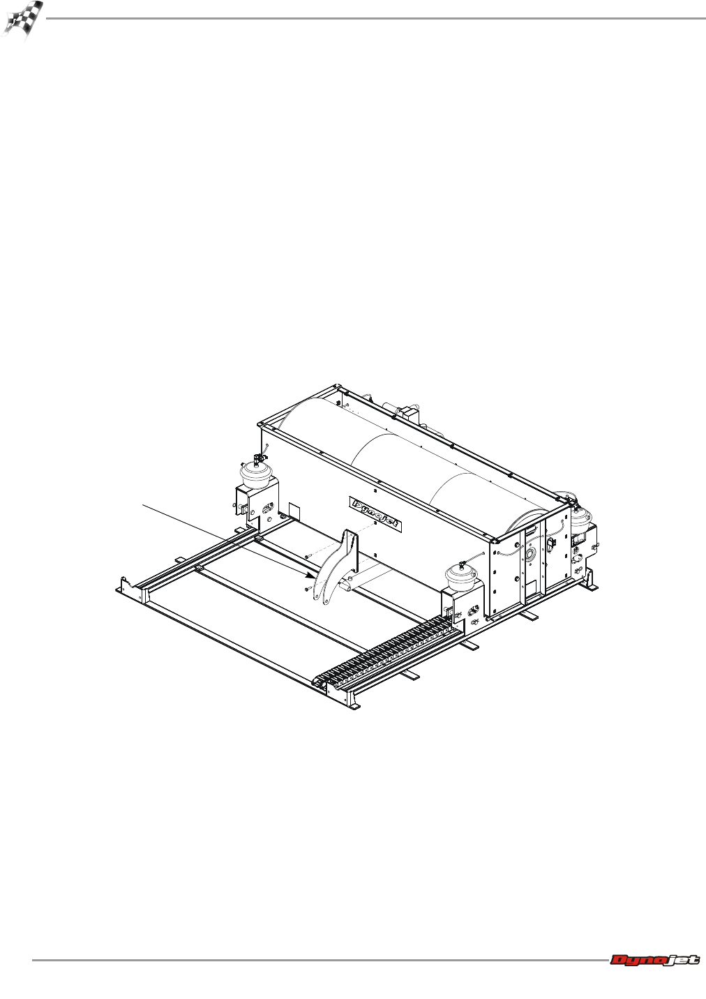
1 Secure the dyno cylinder mount to the dyno using two 3/8-16 x 1.5-inch bolts.
Figure 3-14: Secure the Dyno Cylinder Mount to the Dyno
AD346
dyno cylinder mount