
Installation Guide Owner's manual
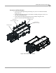
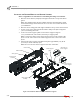
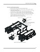
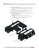
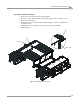
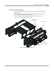
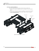
Table Of Contents
- Cover
- Copyright
- Table of Contents
- Warnings
- 1 - Specifications and Operating Requirements
- 2 - Stationary Dyno Installation
- 3 - 4WD Dyno Installation
- Unpacking and Inspecting the Dyno
- Track Assembly
- Dyno Installation
- Cable Routing
- Identifying the Cables
- Routing the Cables—Without the Eddy Current Brakes
- Wiring the Breakout Board—Without the Eddy Current Brakes
- Routing the Cables—With One Eddy Current Brake
- Wiring the Breakout Board—With One Eddy Current Brake
- Routing the Cables—With Two Eddy Current Brakes
- Wiring the Advanced Breakout Board—With Two Eddy Current Brakes
- Hydraulic Movement Installation
- Air Can Sleeve
- 4WD Dyno Movement Test
- Bridge Installation—Stationary Dyno
- Bridge Installation—4WD Dyno
- Deck Installation
- Logo Panel Installation
- 4 - Eddy Current Brake Installation
- Eddy Current Brake Installation
- Before Installing the Eddy Current Brake: Verify Optimal Brake Cooling
- Before Installing the Eddy Current Brake: Verify Mounting Holes
- Unpacking the Eddy Current Brake
- Installing the Temperature Sensor
- Installing the Bearing, Splined Shaft, and Driveline Assembly
- Installing the Eddy Current Brake
- Installing the Load Cell
- Installing the Front and Rear Brake Covers and Theta Controller
- Torque Module Installation
- Load Cell Calibration
- Eddy Current Brake Installation
- 5 - Side Deck Assembly Installation
- 6 - Basic Dyno Operation
- A - Red Head Anchor Installation
- B - Power Requirements and Installation
- C - Stationary Dyno Upgrade
- D - Bridge Extension Assembly
- E - Interface Roller Assembly Installation
- F - Torque Values
- Index
Above Ground Model 424x/424xLC
2
Automotive Dynamometer Installation Guide
CHAPTER 3
Bridge Installation—Stationary Dyno
3-36
INSTALLING THE RUNNER MOUNTS AND RUNNER SUPPORTS
Refer to Appendix D for instructions on installing the bridge extension kit.
1 Place the runner mount (z-shaped) with eight round holes on top of the drum
guard.
Note: The standard runner mount is smaller than the extended runner mount
used with the bridge extension kit. Be sure to use the correct runner mount for
your installation.
2 Place the runner clamp plate with eight round holes on top of the runner mount.
3 Loosely secure each runner mount and runner clamp to the dyno using three
3/8 x 1.5-inch flange hex bolts.
4 Secure two runner support pillars to each runner support using two
1/2 x 3-inch hex bolts, lock washers, and nuts per support pillar.
Note: Use the inner holes on the runner support closest to the outside of the
dynos. Use the outer holes on the runner support closest to the center of the
dynos.
5 Stand up the runner support assemblies and place approximately 119.38 cm
(47.00 in.) from the stationary dyno.
Note: Do not secure the runner support to the floor at this time.
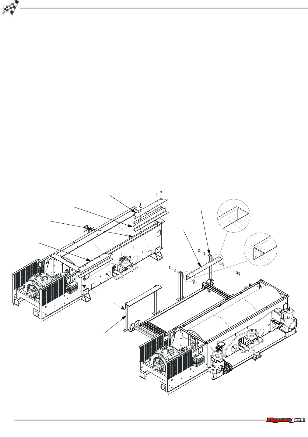
Figure 3-24: Install the Runner Mounts and Runner Supports
AD491
runner mount
assembly
runner clamp
runner mount
runner
support
runner support
pillar
runner support
assembly
drum guard
119.38cm
(47.00 in.)
inner holes on
runner support
outer holes on
runner support