
Installation Guide Owner's manual
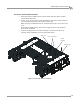
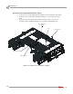
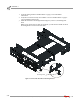
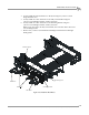
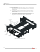
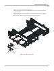
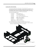
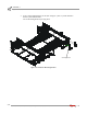
Table Of Contents
- Cover
- Copyright
- Table of Contents
- Warnings
- 1 - Specifications and Operating Requirements
- 2 - Stationary Dyno Installation
- 3 - 4WD Dyno Installation
- Unpacking and Inspecting the Dyno
- Track Assembly
- Dyno Installation
- Cable Routing
- Identifying the Cables
- Routing the Cables—Without the Eddy Current Brakes
- Wiring the Breakout Board—Without the Eddy Current Brakes
- Routing the Cables—With One Eddy Current Brake
- Wiring the Breakout Board—With One Eddy Current Brake
- Routing the Cables—With Two Eddy Current Brakes
- Wiring the Advanced Breakout Board—With Two Eddy Current Brakes
- Hydraulic Movement Installation
- Air Can Sleeve
- 4WD Dyno Movement Test
- Bridge Installation—Stationary Dyno
- Bridge Installation—4WD Dyno
- Deck Installation
- Logo Panel Installation
- 4 - Eddy Current Brake Installation
- Eddy Current Brake Installation
- Before Installing the Eddy Current Brake: Verify Optimal Brake Cooling
- Before Installing the Eddy Current Brake: Verify Mounting Holes
- Unpacking the Eddy Current Brake
- Installing the Temperature Sensor
- Installing the Bearing, Splined Shaft, and Driveline Assembly
- Installing the Eddy Current Brake
- Installing the Load Cell
- Installing the Front and Rear Brake Covers and Theta Controller
- Torque Module Installation
- Load Cell Calibration
- Eddy Current Brake Installation
- 5 - Side Deck Assembly Installation
- 6 - Basic Dyno Operation
- A - Red Head Anchor Installation
- B - Power Requirements and Installation
- C - Stationary Dyno Upgrade
- D - Bridge Extension Assembly
- E - Interface Roller Assembly Installation
- F - Torque Values
- Index
4WD DYNO INSTALLATION
Deck Installation
Version 8 Above Ground Model 424x/424xLC
2
Automotive Dynamometer Installation Guide
3-47
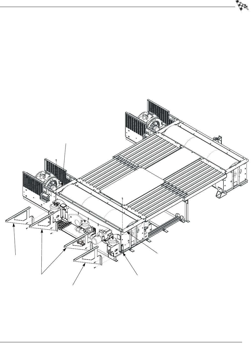
4 Loosely install the inner deck braces to the dyno using two 3/8-16 x 1.5-inch
flange hex bolts each.
5 Loosely install one outer deck brace to the eddy current brake using two
3/8-16 x 1.5-inch flange hex bolts, washers, and nuts.
6 Loosely install one outer deck brace to the mounting bracket using two
3/8-16 x 1.5-inch flange hex bolts, washers, and nuts.
Note: If you do not have an eddy current brake, the outer deck brace will secure
to a mounting bracket.
7 Remove one 3/8-16 x 1.25-inch button-head flange bolt from the left and right
drum guards.
Figure 3-33: Install the Deck Braces
AD500
mounting bracket
outer brace
inner brace
outer brace
right drum guard
left drum guard