
Installation Guide Owner's manual
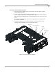
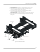
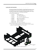
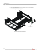
Table Of Contents
- Cover
- Copyright
- Table of Contents
- Warnings
- 1 - Specifications and Operating Requirements
- 2 - Stationary Dyno Installation
- 3 - 4WD Dyno Installation
- Unpacking and Inspecting the Dyno
- Track Assembly
- Dyno Installation
- Cable Routing
- Identifying the Cables
- Routing the Cables—Without the Eddy Current Brakes
- Wiring the Breakout Board—Without the Eddy Current Brakes
- Routing the Cables—With One Eddy Current Brake
- Wiring the Breakout Board—With One Eddy Current Brake
- Routing the Cables—With Two Eddy Current Brakes
- Wiring the Advanced Breakout Board—With Two Eddy Current Brakes
- Hydraulic Movement Installation
- Air Can Sleeve
- 4WD Dyno Movement Test
- Bridge Installation—Stationary Dyno
- Bridge Installation—4WD Dyno
- Deck Installation
- Logo Panel Installation
- 4 - Eddy Current Brake Installation
- Eddy Current Brake Installation
- Before Installing the Eddy Current Brake: Verify Optimal Brake Cooling
- Before Installing the Eddy Current Brake: Verify Mounting Holes
- Unpacking the Eddy Current Brake
- Installing the Temperature Sensor
- Installing the Bearing, Splined Shaft, and Driveline Assembly
- Installing the Eddy Current Brake
- Installing the Load Cell
- Installing the Front and Rear Brake Covers and Theta Controller
- Torque Module Installation
- Load Cell Calibration
- Eddy Current Brake Installation
- 5 - Side Deck Assembly Installation
- 6 - Basic Dyno Operation
- A - Red Head Anchor Installation
- B - Power Requirements and Installation
- C - Stationary Dyno Upgrade
- D - Bridge Extension Assembly
- E - Interface Roller Assembly Installation
- F - Torque Values
- Index
4WD DYNO INSTALLATION
Logo Panel Installation
Version 8 Above Ground Model 424x/424xLC
2
Automotive Dynamometer Installation Guide
3-51
. . . . . . . . . . . . . . . . . . . . . . . . . . . . . . . . . . .
LOGO PANEL INSTALLATION
If you did not install the eddy current brakes, you will install four logo panels, two on
the stationary dyno and two on the 4WD dyno using the instructions in this section. If
you installed the eddy current brakes, use the following instructions to install one
logo panel on each dyno. Refer to “Installing the Top and Logo Panel Covers” on page
4-20 to install the logo panel covers on the eddy current brake.
You will need the following parts:
• 21200004 Mounting Bracket (4)
• 21200009 Lower Mounting Bracket (2)
• 36491100 Nut, 7/16-14, Hex, Grade-5 (4)
• 36561045 Screw, 1/4-20 x 5/8", Pan-Head, Torx (10)
• 36591670 Bolt, 7/16-14 x 1", Hex (4)
• 36933100 Washer, 7/16", Flat, Steel (4)
• 61100001 Logo Panel Assembly (2)
• DM150-011-002 Washer, 3/8", Flat (8)
• DM150-019-008 Bolt, 3/8-16 x 3/4", Hex (8)
Repeat the following steps for each logo panel being installed to the dyno.
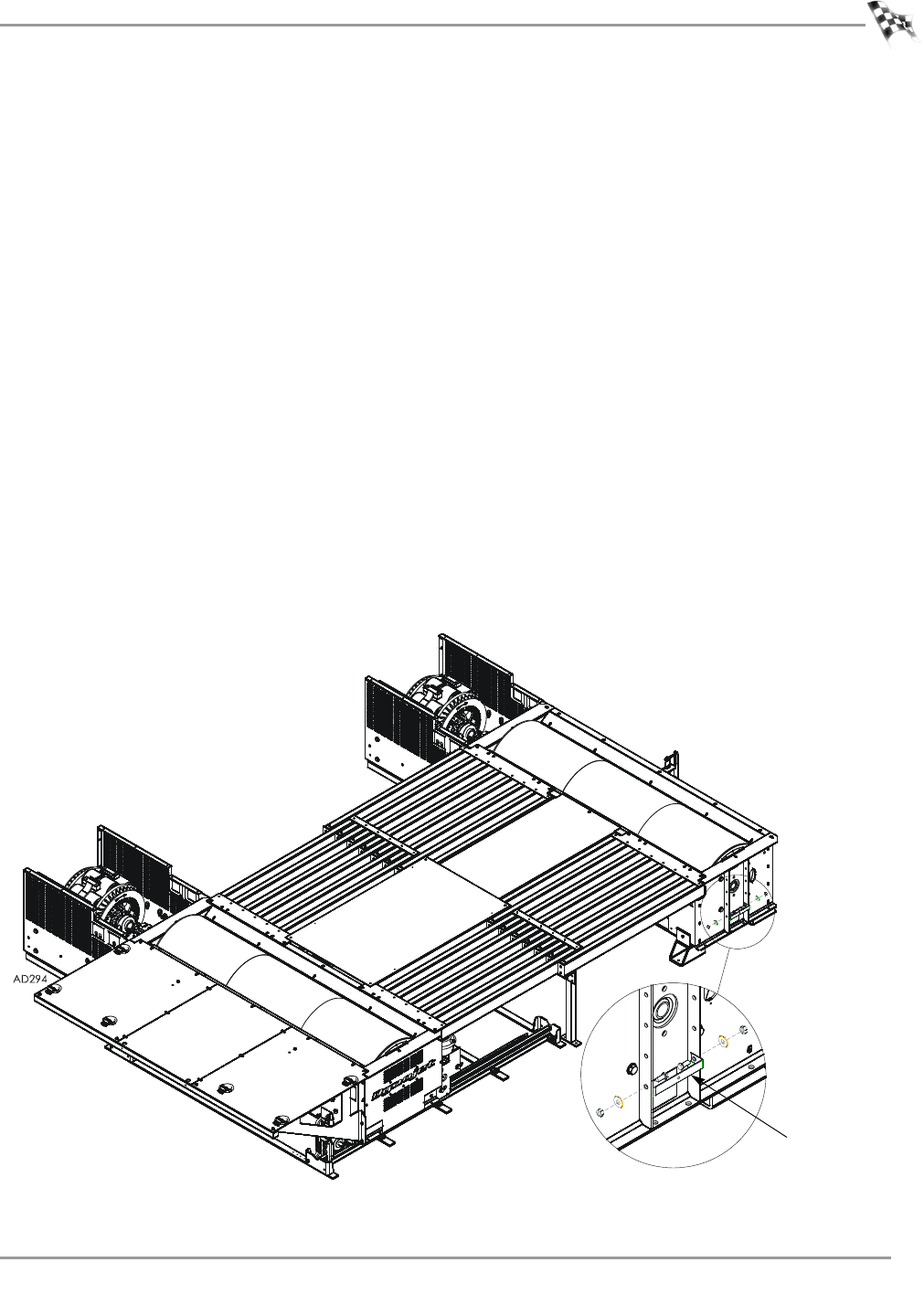
1 Secure each lower mounting bracket to the dyno using two 7/16-14 x 1-inch hex
bolts, two 7/16-inch flat washers, and two 7/16-14 nuts.
Figure 3-37: Install the Lower Mounting Bracket
lower mounting
bracket