©2007-2011 Dynojet Research, Inc. All Rights Reserved. Pre-Installation Guide for Model 224 and 424 Automotive Dynamometers This manual is copyrighted by Dynojet Research, Inc., hereafter referred to as Dynojet, and all rights are reserved. This manual, and the software described in it, is furnished under license and may only be used or copied in accordance with the terms of such license.
TABLE OF CONTENTS Warnings . . . . . . . . . . . . . . . . . . . . . . . . . . . . . . . . . . . . . . . . . . . . . . . . iii Dyno Pre-Installation Information Introduction . . . . . . . . . . . . . . . . . . . . . . . . . . . . . . . . . . . . . . . . . . . . . . . . . . . 2 Conventions Used In This Manual . . . . . . . . . . . . . . . . . . . . . . . . . . . . . . . . 2 Technical Support . . . . . . . . . . . . . . . . . . . . . . . . . . . . . . . . . . . . . . . . . . . . 2 Your Dyno Room . . . . . .
TA B L E O F C O N T E N T S Above Ground Model 424x Dyno . . . . . . . . . . . . . . . . . . . . . . . . . . . . . . . . 19 Chassis Specifications . . . . . . . . . . . . . . . . . . . . . . . . . . . . . . . . . . . . . . . . . Room Layout—Above Ground Model 424x Dyno with Lift . . . . . . . . . . . . . In Ground Model 424x Dyno . . . . . . . . . . . . . . . . . . . . . . . . . . . . . . . . . . . Pit Specifications . . . . . . . . . . . . . . . . . . . . . . . . . . . . . . . . . . . . . . . . . . . .
WARNINGS Disclaimers Dynojet Research, Inc. (Dynojet) makes no representation or warranties with respect to the contents hereof and specifically disclaims any implied warranties of merchantability for any particular purpose. Dynojet reserves the right to revise this publication and to make changes from time to time in the content hereof without obligation of Dynojet to notify any person of such revision or changes.
WA R N I N G S Electrostatic Discharge Precautions Electrostatic Discharge Electrostatic Discharge (ESD), or static shock, can damage electronic components within the dynamometer. The damage may occur at the time of an ESD occurrence, or the shock may degrade the component, resulting in a premature component failure later. To avoid ESD damage, always practice good ESD control precautions when servicing the dynamometer.
WA R N I N G S Other Potential Hazards The AC power outlet shall be installed near the equipment and it shall be easily accessible to allow for disconnect before service. The dynamometer should be located in a well ventilated area. There is a carbon monoxide hazard with all internal combustion engines. Engine exhaust contains poisonous carbon monoxide gas. Breathing it could cause death. Any dyno room design must incorporate sufficient exhaust extraction.
DYNO PRE-INSTALLATION INFORMATION Thank you for your interest in Dynojet’s Automotive Dynamometers. Dynojet’s software and dynamometers will give you the power to get the maximum performance out of vehicles you evaluate. Whether you are new to the benefits of a chassis dynamometer or an experienced performance leader, the repeatability and diagnostic tools of WinPEP 7 software and a Dynojet dynamometer (dyno) will give you the professional results you are looking for.
DYNO PRE-INSTALLATION INFORMATION Introduction INTRODUCTION ................................... Thank you for your interest Dynojet’s Automotive Dynamometers. Before receiving your dyno, please take a moment to read this guide for dyno specifications and requirements, WinPEP 7 requirements, and dyno room set-up. CONVENTIONS USED IN THIS MANUAL The conventions used in this manual are designed to protect both the user and the equipment.
DYNO PRE-INSTALLATION INFORMATION Your Dyno Room YOUR DYNO ROOM ................................... This section is not meant to imply that a dyno room is essential to repeatable results on a Dynojet dynamometer. However, a dyno room with an engine cooling intake fan, exhaust extraction, and noise reduction capabilities can add a new dimension to your shop. SETTING UP A DYNO ROOM A proper dyno room design will help to ensure repeatable, accurate runs.
DYNO PRE-INSTALLATION INFORMATION Specifications and Requirements SPECIFICATIONS AND REQUIREMENTS ................................... The following specifications and requirements apply to all automotive dynos in this manual. Take a moment to review the requirements and make sure you can provide what your dyno will need.
DYNO PRE-INSTALLATION INFORMATION Specifications and Requirements DRILL AND DRILL BIT REQUIREMENTS You will need to provide a drill and drill bit capable of drilling holes in concrete. Refer to Appendix A for more information on installing Red Head Anchors. • drill bit size: 1/2-inch • minimum hole depth: 1 5/8-inch (41.2 mm) ELECTRICAL REQUIREMENTS Each optional eddy current brake requires a power socket that you may order ahead of time and install.
DYNO PRE-INSTALLATION INFORMATION Specifications and Requirements FORKLIFT REQUIREMENTS The crate the dyno is shipped in is eight feet long and will be in the truck the long way. If you have access to a loading dock, you can drag the crate out of the truck and a large forklift is not required. Without a loading dock, you will need a forklift that meets the following requirements. In order to remove the crate from the truck, you will need to provide a forklift with a lift capacity of 6,124 kg (13,500 lb.
DYNO PRE-INSTALLATION INFORMATION Lift Specifications and Requirements LIFT SPECIFICATIONS AND REQUIREMENTS ................................... Dynojet recommends installing the four-post lift before installing your dynamometer. However, if space constraints make it difficult to install the lift first, the dynamometer can be installed before the lift. Dynojet acts as a liaison for Rotary Lifts, to ensure that you receive the proper four-post lift.
DYNO PRE-INSTALLATION INFORMATION Above Ground Model 224x Dyno ABOVE GROUND MODEL 224X DYNO ................................... The following specifications and requirements will help you set up your dyno area and verify you have the requirements necessary to operate your dyno safely.
DYNO PRE-INSTALLATION INFORMATION Above Ground Model 224x Dyno Figure 2: Above Ground Model 224x Dyno Dimensions Version 5 Pre-Installation Guide for Model 224 and 424 Automotive Dynamometers 9
DYNO PRE-INSTALLATION INFORMATION Above Ground Model 224x Dyno ROOM LAYOUT—ABOVE GROUND MODEL 224X WITH LIFT Use the following information to locate various dyno equipment, power outlets, compressed air, and properly set up your dyno room. 338.00 cm (133.00 in.) AD439 locate the following items close to the vehicle: •dyno electronics •computer •monitor 798.00 cm (314.25 in.
DYNO PRE-INSTALLATION INFORMATION In Ground Model 224x Dyno IN GROUND MODEL 224X DYNO ................................... The following specifications and requirements will help you set up your dyno area and verify you have met the requirements necessary to operate your dyno safely. PIT SPECIFICATIONS Before proceeding, take a moment to look over the pit dimensions and requirements for your in ground dyno.
DYNO PRE-INSTALLATION INFORMATION In Ground Model 224x Dyno Figure 4: In Ground Model 224x Dyno Dimensions ROOM LAYOUT—IN GROUND MODEL 224X DYNO Use the following information to locate the necessary dyno equipment, power outlets, compressed air, and properly set up your dyno room. For more detailed information about the pit requirements, refer to the pit specifications (P/N 98219103) you received from your salesman.
DYNO PRE-INSTALLATION INFORMATION Above Ground Model 224xLC Dyno ABOVE GROUND MODEL 224XLC DYNO ................................... The following specifications and requirements will help you set up your dyno area and verify you have the requirements necessary to operate your dyno safely.
DYNO PRE-INSTALLATION INFORMATION Above Ground Model 224xLC Dyno Figure 6: Above Ground Model 224xLC Dyno Dimensions 14 Pre-Installation Guide for Model 224 and 424 Automotive Dynamometers
DYNO PRE-INSTALLATION INFORMATION Above Ground Model 224xLC Dyno ROOM LAYOUT—ABOVE GROUND MODEL 224XLC WITH LIFT Use the following information to locate various dyno equipment, power outlets, compressed air, and properly set up your dyno room. For optimal eddy current brake cooling, the brake should turn in the direction of the arrows on the rotor. The dyno will perform correctly in either direction, but cooling of the rotors may be less effective when turning in the direction opposite of the arrows.
DYNO PRE-INSTALLATION INFORMATION In Ground Model 224xLC Dyno IN GROUND MODEL 224XLC DYNO ................................... The following specifications and requirements will help you set up your dyno area and verify you have met the requirements necessary to operate your dyno safely. PIT SPECIFICATIONS Before proceeding, take a moment to look over the pit dimensions and requirements for your in ground dyno.
DYNO PRE-INSTALLATION INFORMATION In Ground Model 224xLC Dyno Figure 8: In Ground Model 224xLC Dyno Dimensions Version 5 Pre-Installation Guide for Model 224 and 424 Automotive Dynamometers 17
DYNO PRE-INSTALLATION INFORMATION In Ground Model 224xLC Dyno ROOM LAYOUT—IN GROUND MODEL 224XLC DYNO Use the following information to locate the necessary dyno equipment, power outlets, compressed air, and properly set up your dyno room. For more detailed information about the pit requirements, refer to the pit specifications (P/N 98219103) you received from your salesman. For optimal eddy current brake cooling, the brake should turn in the direction of the arrows on the rotor.
DYNO PRE-INSTALLATION INFORMATION Above Ground Model 424x Dyno ABOVE GROUND MODEL 424X DYNO ................................... The following specifications and requirements will help you set up your dyno area and verify you have met the requirements necessary to operate your dyno safely.
DYNO PRE-INSTALLATION INFORMATION Above Ground Model 424x Dyno Figure 10: Above Ground Model 424x Stationary Dyno Dimensions 20 Pre-Installation Guide for Model 224 and 424 Automotive Dynamometers
DYNO PRE-INSTALLATION INFORMATION Above Ground Model 424x Dyno 193.45 cm (76.16 in.) frame, cradle assembly, and deck 130.18 cm (51.25 in.) frame and cradle assembly 73.66 cm (29.00 in.) frame 218.44 cm (86.00 in.) track AD404 218.44 cm (86.00 in.) frame 228.60 cm (90.00 in.) deck 224.15 cm (88.25 in.) track 58.42 cm (23.00 in.) frame 72.07 cm (28.375 in.
DYNO PRE-INSTALLATION INFORMATION Above Ground Model 424x Dyno Figure 12: Above Ground Model 424x Dyno with Bridge and Deck Dimensions 22 Pre-Installation Guide for Model 224 and 424 Automotive Dynamometers
DYNO PRE-INSTALLATION INFORMATION Above Ground Model 424x Dyno ROOM LAYOUT—ABOVE GROUND MODEL 424X DYNO WITH LIFT Use the following information to locate the necessary dyno equipment, power outlets, compressed air, and properly set up your dyno room. 338.00 cm (133.00 in.) AD441 1127.80 cm (444.00 in.) standard 1153.20 cm (454.00 in.) extension provide one 240V outlet for the lift power unit provide compressed air: •to release the air brake •to run the AFR-4 air pump 495.30 cm (195.00 in.
DYNO PRE-INSTALLATION INFORMATION In Ground Model 424x Dyno IN GROUND MODEL 424X DYNO ................................... The following specifications and requirements will help you set up your dyno area and verify you have met the requirements necessary to operate your dyno safely. PIT SPECIFICATIONS Before proceeding, take a moment to look over the pit dimensions and requirements for your in ground dyno.
DYNO PRE-INSTALLATION INFORMATION In Ground Model 424x Dyno Figure 14: In Ground Model 424x Stationary Dyno Dimensions Version 5 Pre-Installation Guide for Model 224 and 424 Automotive Dynamometers 25
DYNO PRE-INSTALLATION INFORMATION In Ground Model 424x Dyno 130.18 cm (51.25 in.) frame and cradle assembly 73.66 cm (29.00 in.) frame 218.44 cm (86.00 in.) frame AD405 224.15 cm (88.25 in.) track 218.44 cm (86.00 in.) track 58.42 cm (23.00 in.) frame only 72.07 cm (28.375 in.
DYNO PRE-INSTALLATION INFORMATION In Ground Model 424x Dyno Figure 16: In Ground Model 424x Dyno with Bridge and Pit Covers Dimensions Version 5 Pre-Installation Guide for Model 224 and 424 Automotive Dynamometers 27
DYNO PRE-INSTALLATION INFORMATION In Ground Model 424x Dyno ROOM LAYOUT—IN GROUND MODEL 424X DYNO Use the following information to locate the necessary dyno equipment, power outlets, compressed air, and properly set up your dyno room. For more detailed information about the pit requirements, refer to the pit specifications (P/N 98219111) you received from your salesman. AD442 provide compressed air: •to release the air brake •to run the AFR-4 air pump 584.20 cm (230.00 in.) frame and covers full out 609.
DYNO PRE-INSTALLATION INFORMATION Above Ground Model 424xLC2 Dyno ABOVE GROUND MODEL 424XLC2 DYNO ................................... The following specifications and requirements will help you set up your dyno area and verify you have met the requirements necessary to operate your dyno safely.
DYNO PRE-INSTALLATION INFORMATION Above Ground Model 424xLC2 Dyno Figure 18: Above Ground Model 424xLC2 Stationary Dyno Dimensions 30 Pre-Installation Guide for Model 224 and 424 Automotive Dynamometers
DYNO PRE-INSTALLATION INFORMATION Above Ground Model 424xLC2 Dyno 193.45 cm (76.16 in.) frame, cradle assembly, and deck 130.18 cm (51.25 in.) frame and cradle assembly 73.66 cm (29.00 in.) frame 218.44 cm (86.00 in.) frame only 321.23 cm (126.47 in.) frame and brake AD349 218.44 cm (86.00 in.) track 228.60 cm (90.00 in.) deck 224.15 cm (88.25 in.) track 65.58 cm (25.82 in.) brake only 80.01 cm (31.50 in.
DYNO PRE-INSTALLATION INFORMATION Above Ground Model 424xLC2 Dyno extension kit dimensions 533.40 cm (210.00 in.) deck full out to lift 426.72 cm (168.00 in.) deck full in to lift 520.70 cm (205.00 in.) frame and deck full out 414.02 cm (163.00 in.) frame and deck full in 508.00 cm (200.00 in.) deck full out to lift 401.32 cm (158.00 in.) deck full in to lift 495.30 cm (195.00 in.) frame and deck full out 388.62 cm (153.00 in.) frame and deck full in 416.56 cm (164.00 in.) Linx option 50.80 cm (20.00 in.
DYNO PRE-INSTALLATION INFORMATION Above Ground Model 424xLC2 Dyno ROOM LAYOUT—ABOVE GROUND MODEL 424XLC2 DYNO WITH LIFT Use the following information to locate the necessary dyno equipment, power outlets, compressed air, and properly set up your dyno room. The eddy current brake is set up to run on the right side of the vehicle. 338.00 cm (133.00 in.) AD443 1127.80 cm (444.00 in.) standard 1153.20 cm (454.00 in.
DYNO PRE-INSTALLATION INFORMATION In Ground Model 424xLC2 Dyno IN GROUND MODEL 424XLC2 DYNO ................................... The following specifications and requirements will help you set up your dyno area and verify you have met the requirements necessary to operate your dyno safely. PIT SPECIFICATIONS Before proceeding, take a moment to look over the pit dimensions and requirements for your in ground dyno.
DYNO PRE-INSTALLATION INFORMATION In Ground Model 424xLC2 Dyno 93.83 cm (36.94 in.) frame and air brake assembly 73.66 cm (29.00 in.) 72.07 cm (28.375 in.) frame to floor AD129 58.42 cm (23.00 in.) frame only 218.44 cm (86.00 in.) frame only 104.14 cm (41.00 in.) eddy current brake 322.58 cm (127.00 in.
DYNO PRE-INSTALLATION INFORMATION In Ground Model 424xLC2 Dyno 130.18 cm (51.25 in.) frame and cradle assembly 218.44 cm (86.00 in.) dyno frame only 321.23 cm (123.47 in.) frame and brake 73.66 cm (29.00 in.) frame AD406 218.44 cm (86.00 in.) track 224.15 cm (88.25 in.
DYNO PRE-INSTALLATION INFORMATION In Ground Model 424xLC2 Dyno 584.20 cm (230.00 in.) frame and covers full out 609.60 cm (240.00 in.) out with bridge extension 469.90 cm (185.00 in.) frame and covers full in 495.30 cm (195.00 in.) in with bridge extension 161.54 cm (63.60 in.) 118.75 cm (46.75 in.) 492.76 cm (194.00 in.) eddy current brake covers 229.87 cm (90.50 in.) AD445 345.44 cm (136.00 in.
DYNO PRE-INSTALLATION INFORMATION In Ground Model 424xLC2 Dyno ROOM LAYOUT—IN GROUND MODEL 424XLC2 DYNO Use the following information to locate the necessary dyno equipment, power outlets, compressed air, and properly set up your dyno room. For more detailed information about the pit requirements, refer to the pit specifications (P/N 98219111) you received from your salesman. The eddy current brake is set up to run on the right side of the vehicle. Linx option 118.75 cm (46.75 in.
DYNO PRE-INSTALLATION INFORMATION Unpacking The Dyno UNPACKING THE DYNO ................................... When you receive your dyno, examine the exterior of the shipping container for any visible damage. If damage is detected at this stage, contact the shipper or Dynojet before proceeding with unpacking. You will need to provide equipment capable of lifting and moving the dyno. Refer to “Forklift Requirements” on page 6 for more information.
DYNO PRE-INSTALLATION INFORMATION Unpacking The Dyno LOCATING THE INSTALLATION GUIDE Your dynamometer installation guides and user guides are located in a manila envelope and secured to the following location. • On a regular 224 dyno, the manual is slipped behind the brake hoses on the brake side of the dyno. • On a 424 dyno, the manuals are in the same location except in the 4WD crate, not in the stationary dyno crate.
APPENDIX A RED HEAD ANCHOR INSTALLATION This appendix contains instructions for installing the Red Head Multi-Set™II Anchors. The anchors will be used to secure the dyno to concrete. To ensure safety and accuracy in the procedures, perform the procedures as they are described. Be sure to read and understand the warnings included in this appendix. WARNINGS Always wear safety glasses and other necessary protective devices or apparel when installing or working with anchors.
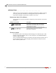
APPENDIX A Installation INSTALLATION ................................... Use the table below to determine the catalog number, drill bit size, minimum hole depth, and setting tool catalog number. catalog number Carbon Steel RM-38/RL-38 (9.5 mm) drill bit size 1/2-inch minimum hole depth 1 5/8-inch (41.2 mm) setting tool catalog number RT-138 Use the following instructions to install the Red Head anchors.
RED HEAD ANCHOR INSTALLATION Installation 3 Using a hammer, drive the anchor flush with the surface of the concrete, or below the surface if the hole depth exceeds minimum embedment. Figure A-3: Red Head Anchor—Drive the Anchor Flush 4 Using a hammer, expand the anchor with the setting tool. The anchor is properly expanded when the shoulder of the setting tool is flush with the top of the anchor. Note: Use only Ramset/Red Head setting tools to insure proper installtion.
APPENDIX B POWER REQUIREMENTS AND INSTALLATION This appendix contains power requirements and installation instructions for the eddy current brake. To ensure safety and accuracy in the procedures, perform the procedures as they are described. Be sure to read and understand the warnings included in this appendix.
APPENDIX B Power Requirements and Installation—North America, Japan, and Locations Using 60 Hz Power POWER REQUIREMENTS AND INSTALLATION—NORTH AMERICA, JAPAN, AND LOCATIONS USING 60 HZ POWER ................................... The following power requirements and instructions are for North America, Japan, and locations using 60 Hz power. Refer to “Power Requirements and Installation— Excluding North America and Japan” on page B-5 for all other locations.
POWER REQUIREMENTS AND INSTALLATION Power Requirements and Installation—North America, Japan, and Locations Using 60 Hz Power TESTING FOR CORRECT VOLTAGES You must test the receptacle for proper voltages before the eddy current brake is connected to the outlet. If the voltage readings do not match the following table, DO NOT connect the brake. You must have a licensed electrician correct the power connection.
APPENDIX B Power Requirements and Installation—North America, Japan, and Locations Using 60 Hz Power HARD WIRING TO THE BUILDING Use the following instructions to wire the brake directly to the building. The brake must connect to a two pole disconnect switch to allow the removal of all power to the brake for servicing. This box may contain fusing, circuit breakers, or the circuit protection may be upstream in the building power system.
POWER REQUIREMENTS AND INSTALLATION Power Requirements and Installation—Excluding North America and Japan POWER REQUIREMENTS AND INSTALLATION—EXCLUDING NORTH AMERICA AND JAPAN ................................... The eddy current brake (excluding North America and Japan) requires a dedicated wall receptacle which must be wired for operation and is included with the brake or may be shipped in advanced in a separate package.
APPENDIX B Power Requirements and Installation—Excluding North America and Japan INSTALLING THE WALL RECEPTACLE The wall receptacle is a single 240 volt 30A dedicated circuit with a ground. Note: The actual wall receptacle may be different from the image shown in Figure B-2; however, the installation instructions are the same. The cable carrying the power to this receptacle should be 4.0 mm2 (ten gauge) or larger. Check with local building codes for the correct size.
POWER REQUIREMENTS AND INSTALLATION Power Requirements and Installation—Excluding North America and Japan TESTING FOR CORRECT VOLTAGES You must test the receptacle for proper voltages before the eddy current brake is connected to the outlet. Using a voltmeter that is capable of measuring AC voltage, measure between the points listed below and verify that the correct voltages are present.
INDEX 224x above ground 1-8 chassis specifications 1-8 dimensions 1-9 room layout 1-10 224x in ground 1-11 chassis specifications 1-11 dimensions 1-12 pit specifications 1-11 room layout 1-12 224xLC above ground 1-13 chassis specifications 1-13 dimensions 1-14 room layout 1-15 224xLC in ground 1-16 chassis specifications 1-16 dimensions 1-17 pit specifications 1-16 room layout 1-18 424x above ground 1-19 chassis specifications 1-19 dimensions, 4WD 1-21 dimensions, bridge/deck 1-22 dimensions, stationary 1-
INDEX disclaimers iii document part number 1-1 drill and drill bit 1-5 dyno room cooling fan 1-3 exhaust extraction 1-3 fire suppression 1-3 E electrical requirements 1-5 electrostatic discharge iv environmental requirements 1-5 ESD precautions iv F fire suppression 1-5 forklift requirements 1-6 H hazards v height 224x above ground 1-8 224x in ground 1-11 224xLC above ground 1-13 224xLC in ground 1-16 424x above ground 1-19 424x in ground 1-24 424xLC2 above ground 1-29 424xLC2 in ground 1-34 I inst
INDEX W warnings iii weight 224x above ground 1-8 224x in ground 1-11 224xLC above ground 1-13 224xLC in ground 1-16 424x above ground 1-19 424x in ground 1-24 424xLC2 above ground 1-29 424xLC2 in ground 1-34 width 224x in ground 1-11 224xLC above ground 1-8, 1-13 224xLC in ground 1-16 424x above ground 1-19 424x in ground 1-24 424xLC2 above ground 1-29 424xLC2 in ground 1-34 Version 5 Pre-Installation Guide for Model 224 and 424 Automotive Dynamometers Index-iii