
Installation Guide Owner manual


3-5
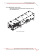
4WD DYNO INSTALLATION
Track Assembly
Version 1 Above Ground Model 424x/424xLC
2
Automotive Dynamometer Installation Guide
TRACK ASSEMBLY
The stationary dyno must be installed before proceeding with the 4WD dyno
installation. Refer to chapter 2 for stationary dyno installation instructions.
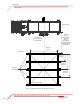
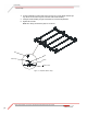
Before installing the track assembly, layout the entire track assembly using the
following instructions and Figure 3-1 for position and alignment.
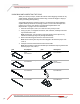
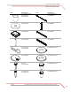
You will need the following parts:
• 37513200 Anchor, Redhead, 3/8" (10)
• 37518200 Redhead Anchor Installation Tool
1 Line up the center line of the track assembly with the center line of the stationary
dyno.
2 Measure the following distances and set the track assembly as listed below and
shown in Figure 3-1.
• The track assembly should be 128.27 cm (50.50 in.) from the stationary dyno
without the extension kit and 153.67 cm (60.50 in.) with the extension kit.
• The distance between the inside of the rails should be 184.15 cm
(72.50-inches +/- 0.06 in.).
• The distance from the first rail tie assembly to the first rail tie is 49.37 cm
(19.438 in.).
• The distance from the first rail tie assembly to the second rail tie is 103.82 cm
(40.875 in.).
• The distance from the first rail tie assembly to the third rail tie is 158.28 cm
(62.313 in.).
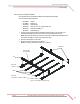
3 Verify the track assembly is square. Measure from corner to corner and verify
these measurements are equal.
4 Mark and drill all ten holes, five on each side of the track assembly.
5 Set the track assembly aside.
6 Install the ten Red Head anchors. Refer to Appendix A for installation
instructions.