©2004 Dynojet Research, Inc. All Rights Reserved. Flow Meter User Guide This manual is copyrighted by Dynojet Research, Inc., hereafter referred to as Dynojet, and all rights are reserved. This manual, as well as the software described in it, is furnished under license and may only be used or copied in accordance with the terms of such license. This manual is furnished for informational use only, is subject to change without notice, and should not be construed as a commitment by Dynojet.
TABLE OF CONTENTS Flow Meter Testing Introduction . . . . . . . . . . . . . . . . . . . . . . . . . . . . . . . . . . . . . . . . . . . . . . . . . . . . 2 Warnings . . . . . . . . . . . . . . . . . . . . . . . . . . . . . . . . . . . . . . . . . . . . . . . . . . . . . 2 Conventions Used In This Manual . . . . . . . . . . . . . . . . . . . . . . . . . . . . . . . . . . 2 Technical Support . . . . . . . . . . . . . . . . . . . . . . . . . . . . . . . . . . . . . . . . . . . . . . 2 Flow Meter Testing . . .
FLOW METER TESTING This document provides instructions for performing flow meter tests on your air/fuel ratio pump (air pump). To ensure safety and accuracy in the procedures, perform the procedures as they are described.
FLOW METER Introduction INTRODUCTION ................................... Flow Meter testing is a valuable troubleshooting tool. Testing with the flow meter will help you determine if you need to rebuild the air pump. Be sure to read and follow all warnings found throughout this manual. For more detailed information on the air pump, refer to the Air Fuel Ratio Module Installation and User Guide (P/N 98295110). WARNINGS The sensor and the copper sample tube are hot.
USER GUIDE Flow Meter Testing FLOW METER TESTING ................................... This section describes the five test point procedures using the flow meter to test the air pump.
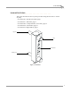
FLOW METER Flow Meter Testing ASSEMBLING THE FLOW METER Before performing any tests on the air pump you will need to assemble the flow meter. Everything you need to correctly assemble the flow meter is included with your flow meter kit (P/N 34803001). 1 Knead the bag containing the o-rings and the lubricant until all three o-rings are coated. Note: Be careful not to stretch or tear the o-rings. 2 3 Place an o-ring on each plug.
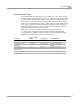
USER GUIDE Flow Meter Testing FLOW METER TEST POINTS The following table describes the flow meter readings for a new, rebuilt, or dirty air pump in liters/minute. Perform all of the tests outlined in this manual and fill out your results in the data tables on page 16. When you have completed all of the tests, compare your results with the following table. If the flow meter reading is equal to or lower than the dirty air pump reading, follow the steps outlined in the action required column of the table.
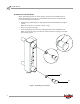
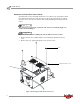
FLOW METER Flow Meter Testing REMOVING THE PUMP HEAD SERVICE COVER You will need to remove the pump head service cover before you can perform certain tests with the flow meter. It is not necessary to remove the sensor when you remove the service cover, but exercise extreme caution when handling and working near the sensor. The sensor is not covered by a warranty. The sensor is extremely fragile. Use caution when handling it. The sensor is hot. Before touching the sensor make sure it has cooled.
USER GUIDE Flow Meter Testing CHECKING TEST POINT ONE—OVERALL SYSTEM FLOW The first test point checks the flow into the entire system. Note: Always keep the flow meter upright when testing. 1 2 3 4 Attach the exhaust inlet hose to the top port of the flow meter. Turn the air pump on. Record the flow meter reading in a data table on page 16. Turn the air pump off.
FLOW METER Flow Meter Testing CHECKING TEST POINT TWO—FILTER FLOW Test point two is comprised of two tests. The first part of this test checks the air flow in the entire system except for the filter assembly. The second part of this test checks the filter assembly for leaks. AIR FLOW 1 2 3 4 5 6 Remove the sensor hose from the filter. Attach the end of the sensor hose to the top port of the flow meter. Attach the short hose, included with your flow meter kit, to the bottom port of the flow meter.
USER GUIDE Flow Meter Testing FILTER ASSEMBLY 1 2 3 4 5 Remove the filter bowl hose from the filter bowl. Plug the filter bowl fitting with your finger. Plug the exhaust inlet hose with your finger. Turn the air pump on. Record the flow meter reading in a data table on page 16. Note: The flow meter reading should be zero. If the flow is more than two liters/minute the filter bowl has a significant leak. 6 7 8 9 10 Turn the air pump off.
FLOW METER Flow Meter Testing CHECKING TEST POINT THREE—PUMP INLET PORT, SENSOR SIDE Test point three tests between the sensor block and the inlet port on the pump head. The first part of test point three checks the flow through the filter and the sensor block and the second part of test point three checks the sensor and sensor block for leaks. FILTER FLOW 1 Remove the pump inlet hose from the pump. Note: The pump inlet hose is the wider hose inside the air pump.
USER GUIDE Flow Meter Testing SENSOR BLOCK ASSEMBLY The sensor is not covered by a warranty. The sensor is extremely fragile. Use caution when handling it. The sensor is hot. Before touching the sensor make sure it has cooled. 1 2 With the flow meter still attached, remove the sensor hose from the filter. Plug the sensor hose with your finger. 3 4 Turn the air pump on. Record the flow meter reading in a data table on page 16. Note: The flow meter reading should be zero.
FLOW METER Flow Meter Testing CHECKING TEST POINT FOUR—LEFT OUTFLOW Testing the outflow allows you to determine the efficiency of the left pump head. 1 2 3 4 Remove the left outflow hose from the left outflow catch bottle. Attach the left outflow hose to the bottom port of the flow meter. Turn the air pump on. Record the flow meter reading in a data table on page 16. If the flow meter reading is below the testing range, rebuild the pump head.
USER GUIDE Flow Meter Testing CHECKING TEST POINT FIVE—RIGHT OUTFLOW Testing the outflow allows you to determine the efficiency of the right pump head. 1 2 3 4 Remove the right outflow hose from the right outflow catch bottle. Attach the right outflow hose to the bottom port of the flow meter. Turn the air pump on. Record the flow meter reading in a data table on page 16. If the flow meter reading is below the testing range, rebuild the pump head.
FLOW METER Flow Meter Testing INTERPRETING YOUR FLOW METER RESULTS The results from the flow meter tests indicate what maintenance needs to be performed on the air pump. Refer to the following table to evaluate the test results. If the flow meter reading is equal to or lower than the dirty air pump reading, follow the steps outlined in the action required column of the table. Pump head rebuild kits (P/N 79190003) are available from Dynojet.
USER GUIDE Flow Meter Testing REPLACING THE PUMP HEAD SERVICE COVER Before replacing the pump head service cover be sure to perform any necessary maintenance procedures. The sensor is not covered by a warranty. The sensor is extremely fragile. Use caution when handling it. The sensor is hot. Before touching the sensor make sure it has cooled. 1 2 Carefully flip the pump head service cover back over the sensor. Secure the pump head service cover using the four No. 2 phillips head screws removed earlier.
FLOW METER Flow Meter Testing DATA TABLES Use these tables to keep a record of your flow meter readings. Compare your results with the table on page 14.