©1993-2001 Dynojet Research, Inc. All Rights Reserved. Optical RPM Sensor Installation Guide. This manual is copyrighted by Dynojet Research, Inc., hereafter referred to as Dynojet, and all rights are reserved. This manual, as well as the software described in it, is furnished under license and may only be used or copied in accordance with the terms of such license.
TABLE OF CONTENTS List of Figures. . . . . . . . . . . . . . . . . . . . . . . . . . . . . . . . . . . . . . . . . . . . . iii Chapter 1 Optical RPM Sensor Installation Conventions Used In This Manual . . . . . . . . . . . . . . . . . . . . . . . . . . . . . . . . . . 1-1 Technical Support . . . . . . . . . . . . . . . . . . . . . . . . . . . . . . . . . . . . . . . . . . . . . . . 1-2 Parts List . . . . . . . . . . . . . . . . . . . . . . . . . . . . . . . . . . . . . . . . . . . . . . . . . . . . . . .
LIST OF FIGURES Figure 1-1: Optical RPM Sensor Assembly Parts . . . . . . . . . . . . . . . . . . . . . . . 1-2 Figure 1-2: Attach Reflective Tape To Harmonic Balancer . . . . . . . . . . . . . . . 1-3 Figure 1-3: Hardware Stack—Optical Sensor and Power Lead . . . . . . . . . . . 1-3 Figure 1-4: Optical Sensor—Mount To Magnetic Base . . . . . . . . . . . . . . . . . 1-4 Figure 1-5: Optical Sensor—Verify Position And Proper Function . . . . . . . . . 1-5 Figure 1-6: Error Message . . . . . . . . . . . . . .
CHAPTER 1 OPTICAL RPM SENSOR INSTALLATION This document provides instructions for installing the Optical RPM Sensor. To ensure safety and accuracy in the procedures, perform the procedures as they are described. This manual will walk you through the installation procedures, running WinPEP and using the tachometer to verify proper function, and describe how to make any necessary adjustments.
CHAPTER 1 TECHNICAL SUPPORT For assistance, please contact Dynojet Technical Support at 1-800-992-4993, or write to Dynojet at 2191 Mendenhall Drive, North Las Vegas, NV 89031. Visit us on the World Wide Web at www.dynojet.com where Dynojet provides state of the art technical support, on-line shopping, 3D visualizations, and press releases about our latest product line. PARTS LIST The following table lists all of the parts included in the Optical RPM Sensor Installation kit.
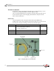
OPTICAL RPM SENSOR INSTALLATION Installation INSTALLATION ................................... This section describes the procedures for installing the optical RPM sensor. CONNECTING THE OPTICAL RPM SENSOR 1 2 Cut a one inch strip of reflective tape from the roll provided. Clean a flat section of the harmonic balancer. Attach the strip of reflective tape. Note: High RPM engines will require a longer piece of reflective tape; use a 1.25-1.5-inch strip of tape.
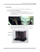
CHAPTER 1 Installation 5 6 Mount the optical sensor to the magnetic base. The base is adjustable to allow the sensor to be oriented in many directions. Attach the other end of the optical sensor lead into the optical sensor. optical sensor magnetic base optical sensor lead Figure 1-4: Optical Sensor—Mount To Magnetic Base OPTICAL SENSOR SET UP AND ADJUSTMENT 1 2 Disconnect the negative battery cable. This will prevent the vehicle from starting.
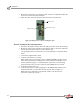
OPTICAL RPM SENSOR INSTALLATION Installation 7 Verify both the green and red lights on the optical sensor are on. Both lights will be on if the optical sensor in the correct position. The red lens on the sensor must be pointed at the reflective tape. If the red light is not on, the sensor will need to be relocated or adjusted. This condition indicates that the sensor can not see the reflective tape. Disconnect the negative battery cable any time you work under the front of the vehicle.
CHAPTER 1 Running WinPEP RUNNING WINPEP ................................... Use the following steps to run WinPEP, use the tachometer to verify the optical sensor is functioning properly, and make a test run Note: Depending on your version of WinPEP, the appearance of the windows and messages may be slightly different than the ones used in this example. STARTING WINPEP 1 2 Double-click the WinPEP icon on the desktop. Click the Make Run icon in the work space toolbar to display the Make Run window.
OPTICAL RPM SENSOR INSTALLATION Running WinPEP SELECTING A NAME Use the following procedures to set up your Make Run window and make a test run. In this example we will use a Chevy Corvette owned by Larry Hall. 1 Select the Make. 1a Select Chevy from the file structure. file structure Figure 1-8: Make Run Window—Select The Make 2 Select the Model. If your model is not present in the file structure, you will need to add your model to the list. 2a Press Insert to insert a new model.
CHAPTER 1 Running WinPEP 3 Type the name of the owner. The name can be one to eight characters long with no spaces and use small or capital letters. Example: LARRY 4 Click OK to continue. Figure 1-10: Make Run Window—Select Name Using the Corvette as an example, the Make Run window should look like Figure 1-11 below.
OPTICAL RPM SENSOR INSTALLATION Running WinPEP EDITING THE NOTES AND PARAMETERS You will need to fill in the Make Run data necessary for making a dyno run. We will continue using the Corvette as an example. Note: Absolute Pressure, Room Air Temperature, and Relative Humidity are automatically determined by DynoWare’s Atmospheric module and cannot be changed. NEXT RUN NAME Type in the name of the run. Refer to Figure 1-12. The name entered will appear on the printed graph. Example: LARRY.
CHAPTER 1 Running WinPEP PLUG FIRES Enter 360 for the number of plug fires when using the optical RPM sensor. Refer to Figure 1-13. TACHOMETER REDLINE Enter the Tachometer Redline from your vehicle’s tachometer or your owner’s manual. Refer to Figure 1-13. Example: 7,250 RPM = 7.25 This places a redline on the tachometer that appears on the computer screen during a run. If you exceed this redline during your run, the tachometer needle on the computer screen will change colors.
OPTICAL RPM SENSOR INSTALLATION Running WinPEP RUN TYPE Select the type of run you will be performing. Refer to Figure 1-14. A description of each Run Type is listed below. Example: RO run type description RO Roll-On AG All Gear Run FA Fast Acceleration NG Negative Horsepower RUN NOTES Enter up to five lines of information about your run. Example: 4TH GEAR ROLL ON TEST, LARRY HALL’S 1994 CORVETTE, ZR-1 BEFORE FULL SERVICE, TUNE-UP.
CHAPTER 1 Running WinPEP OPTIONAL MAKE RUN SETTINGS Auto Download—automatically saves a delimited text file in a numbers data format after each run. The name of the file will be the same as the run with a DAT extension and will be stored in the same directory as the run. Hold BaseLine—when this option is checked the first run in the selection list or the first run made is held in the number one slot on the graph for comparison.
OPTICAL RPM SENSOR INSTALLATION Running WinPEP The following gauges window will appear. The tachometer gauge will be used to verify the optical RPM sensor is functioning properly. Refer to Make a Test Run, step 2 on page 1-14 for instructions on testing the tachometer. Figure 1-16: Make Run Window—Gauges PREPARING FOR A RUN Use the following procedures and safety checks to prepare for a run.
CHAPTER 1 Running WinPEP ENGINE WARM UP 3 Warm the vehicle’s engine and drivetrain before beginning testing. Consistent engine temperatures will assure your runs are repeatable. FOLLOWING ENGINE WARM UP 4 5 6 When you exit a vehicle while still on the dyno, always leave the vehicle in Park (automatic transmission) or in first gear (manual transmission); turn the engine off; and make sure both the vehicle emergency brake and the dyno brake are on.
OPTICAL RPM SENSOR INSTALLATION Running WinPEP 3 Stop the vehicle. 3a Remove your foot from the accelerator pedal. 3b Take the vehicle out of gear (manual transmission only). 3c Press brake button on the hand-held pendant to stop the dyno drums. Do NOT use the vehicle’s own brakes to slow the dyno drums! Using only the vehicle’s brake to stop the drums will severely over stress the vehicle’s brake parts. The vehicle’s brakes should be used in emergency stop situations only.