
Installation Guide User guide


Model SD12 Scooter Dynamometer Installation Guide
CHAPTER 1
Introduction
1-2
. . . . . . . . . . . . . . . . . . . . . . . . . . . . . . . . . . .
INTRODUCTION
Before installing your dyno, please take a moment to read this guide for installation
instructions, dyno features, and other important information.
This guide is designed to be a reference tool in your everyday work and includes the
following chapters and information:
SPECIFICATIONS AND OPERATING REQUIREMENTS
This chapter describes the requirements and specifications for the dyno.
INSTALLATION
This chapter describes the procedures for installing the dyno.
BASIC DYNO OPERATION
This chapter describes basic dyno operating procedures.
CONVENTIONS USED IN THIS MANUAL
The conventions used in this manual are designed to protect both the user and the
equipment.
TECHNICAL SUPPORT
For assistance, please contact Dynojet Technical Support at 1-800-992-3525, or write
to Dynojet at 2191 Mendenhall Drive, North Las Vegas, NV 89081.
Visit us on the World Wide Web at www.dynojet.com and www.winpep.com where
Dynojet provides state of the art technical support, on-line shopping, 3D
visualizations, and press releases about our latest product lines.
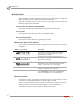
example of convention description
The Caution icon indicates a potential hazard to the
dynamometer equipment. Follow all procedures
exactly as they are described and use care when
performing all procedures.
The Warning icon indicates potential harm to the
person performing a procedure and/or the
dynamometer equipment.
#
RECORD
The Record # icon reminds you to record your
dynamometer and/or eddy current brake (retarder)
number on the inside cover of this manual.
Bold Highlights items you can select on in the software
interface, including buttons and menus.
The arrow indicates a menu choice. For example,
“select File
Open” means “select the File menu,
then select the Open choice on the File menu.”