©1993-1999 Dynojet Research, Inc. All Rights Reserved. Installation Guide for Snowmobile Dynamometers. This manual is copyrighted by Dynojet Research, Inc., hereafter referred to as Dynojet, and all rights are reserved. This manual, as well as the software described in it, is furnished under license and may only be used or copied in accordance with the terms of such license.
Contents Chapter 1 ..............................................1 - 1 Setup and Maintenance Uncrating the Dyno ................................................................1 - 1 Dyno Maintenance .................................................................1 - 7 Chapter 2 ..............................................2 - 1 Hardware Installation DynoWare EX+........................................................................2 - 1 Atmospheric Sensing Module.........................................
1ii Document #98260100
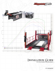
Chapter 1 Setup and Maintenance of the Sled Dyno Uncrating the dyno Step 1 Look for any external damage to the crate. If any damage is present contact the carrier and Dynojet. Step 2 Remove the top of the crate. Step 3 Remove the sides of the crate.
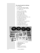
The crate will contain the following.
Step 4 Remove all components except the dyno and check the contents. Step 5 Remove bolts holding down the dyno. Install handle into receivers and secure with 1/4" bolts. Raise the handle to engage the wheel so the dyno will roll. Step 6 To lift the dyno off the crate, use a continuous loop strap and hook on all four corners of the main frame (Refer to the picture on the next page). Important: Loop the straps so that they cross at the top.
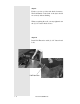
DO NOT LIFT THE DYNO BY THE ARMS ! Step 7 Install the jack with the pin and cotter keys on top and the 3/8” bolt in the bottom. Step 8 Install the brake cover, it attaches with (5) 1/4” button head screws. Two screws of the front, and three screws on the rear.
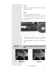
Brake Cover Install the front (2) screws. These screws are accessed from the inside of the brake cover. (Leave the Screws Loose) Install the (3) screws on the back of the Brake Cover.
Step 9 Fit the cover into position and check clearances. The Lift Handle on the back of the dyno should move freely without binding. When everything fits well, you may tighten down the (5) 1/4” button head screwss Step 10 Install Lid Extension with (4) 1/4” button head bolts.
Dyno Maintenance The dyno should get a general inspection every 2 weeks depending on the number of runs made. This inspection should include: Checking all bolts to ensure they are tight. Ensure the sprockets and driver assembly is in good working condition. Examine the plastic driver wheels to ensure that they are in good shape and do not show excessive wear. The chain guards should be removed and the chain tension checked every 300 runs.
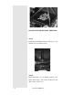
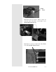
The cover should be removed every 300 runs to ensure the brake is properly adjusted (see next page) and to check the internal components for wear. Use the brake adjustment bolt on the left (shown below) to adjust the Left side brake pad. Loosen the lock nut and screw the adjuster bolt in so that the clearance between the brake pad and the disk is 0.0500". Tighten the lock nut. Do the same to the right side. Check the brake fluid and fill if necessary.
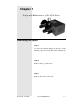
Chapter 2 Hardware Installation DynoWare EX+ The standard dynamometer electronics package is comprised of 4 interconnected modules: System Expansion Connector Atmospheric Sensing Module RPM Module Dynamometer Input/Output Module CPU Module Atmospheric Sensing Module: The atmospheric sensing module measures absolute pressure, air temperature and relative humidity.
RPM Module: The RPM module receives and processes signals from up to 2 inductive pickups for measurement of engine RPM. Each input has an automatic gain circuit to compensate for a wide variance of ignition systems. The green LED glows when the RPM module is receiving power. The amber LED flashes when an RPM signal is detected. A steady flash rate, proportional to engine RPM, indicates a good RPM signal. These connectors are the inputs for both primary and secondary inductive pickup clips.
Dynamometer Input/Output Module: The dynamometer I/O module sends and receives data from the dynamometer and the hand held pendant. The module also contains a buzzer and light which are activated when either the vehicle or dynamometer speed limit is approached. The green LED glows when the dynamometer input/output module is receiving power. The amber LED flashes proportionally to dynamometer drum RPM. This 25-pin receptacle connects to the shielded cable from the dynamometer.
CPU Module: The CPU module contains a 32-bit processor which acquires data from the expansion modules and communicates to the main computer running the WinPEP software. The processor queries the expansion modules to determine their identity and capabilities. The green LED glows when the CPU module is receiving power. The blue LED is lighted when data from the modules is being acquired and saved. One of these connectors is used to communicate to the main computer.
CPU Module: ..... Continued This connector provides a synchronization signal to a 3rd-party data acquisition system. This connector provides 12 Volt DC power to a 3rd-party data acquisition system. This connector accepts 12 Volt DC power from a power supply or battery. The adjacent LED glows bright green when power is properly connected. When this switch is on, power is supplied to all connected modules.
Primary Inductive Pickup Cable (not shown) Remote Switch Breakout Board to DynoWare Cable Cord from Power Supply Computer Serial Port Cable 2-6 Master Document #98226100
Chapter 3 Optional Accessories Installation Several optional accessories are available for the Dynojet Dynamometer. Call Dynojet for more information on these optional accessories. Optional Accessories Driver Carriage This fully adjustable Carriage has several benefits. First, this option allows a dyno owner to hook to any conventionally driven snowmobile. The OEM suspension can be removed and the Driver Carriage will adjust to fit the stock mounting holes.
Contents (A) - Driver Carriage Frame (B) - Front Mount Assembly (C) - Rear Mount Assembly B C A Driver Carriage Set up Step 1 The pins on the Driver Carriage frame should be retracted when you receive it. Fit the Front Carriage Mount to the front of the frame and release the pins. The Front Carriage Mount should be oriented so that it can touch the stop.
Step 2 Mount the Rear Carriage Mount to the Carriage Frame with the (6) 3/8” allen head bolts. The backing plates that the bolts thread into have a left and right side. Note: The Rear Carriage Mount can be mounted in two different configurations depending on your snowmobile. See next page for applications. Backing plates The holes are offset to one side, this is the side that should be closest to the outside on the Carriage Frame.
Application #1 - Polaris - Yamaha - Ski Doo / Bombardier - Arctic Cat Rear Carriage Mount should oriented so that 4 out of the 6 holes are towards the front of the carriage. (The triangular braces are facing towards the Front Carriage Mount) Application #2 - Fast M-10 - AD Boivin - Similar Designs to the above where additional Front Carriage Mount clearance is needed. Rear Carriage Mount should oriented so that 4 out of the 6 holes are towards the rear of the carriage.
Installing the Driver Carriage Step 1 Remove the rear suspension as per manufacturers instructions. Step 2 Due to the varying widths of tunnels, it will be necessary to measure the width between the suspension mounting holes. Step 3 Using the measurements, you must lengthen or shorten the adjustable rods on the Driver Carriage. Remove the adjustable rods by loosening the set screw and “popping” them out with a punch.
Rear Carriage Mount Step 4 Now that you have the adjustable rods removed, loosen the locking nuts on the rods. Adjust the length on the rods equally on each side (front / rear) to reflect the measurements you took earlier. Step 5 Reinstall the adjustable rods into the front and rear Driver Carriage mounts and tighten the set screw.
Step 6 Install the front Driver Carriage mount in the two most forward (towards engine) holes in the tunnel. Note: On some sleds, the Front Carriage Mount idler wheels may interfere with the snowmobile’s drivers. You will need to test fit the Front Carriage Mount to each sled and check the clearances. If there is a clearance issue, you will need to remove the idler wheels from the Front Carriage Mount. Remove the snap rings and remove each idler wheel. The idler wheels will need to be “pressed” off.
Step 7 Retract the spring pins in the Driver Carriage, and then position it in the front mount. Release the spring pins when you have the holes lined up. Step 8 Install the rear mount of the Driver Carriage to the rear mounting holes on the tunnel.
Step 9 The track should be hanging loose at this point, you will need to pre-tension the track with the Driver Carriage. Loosen the bolts that hold the rear mount on the Driver Carriage.
Tighten the center adjuster bolt to pre-tension the track. Note: Do not use the center Driver Carriage adjuster bolt to tension the track. This is for rough adjustment purposes only ! Tighten the (6) bolts that hold the rear mount on the Driver Carriage. Tighten (6) Bolts (3 on each side) Step 10 The track should now be pre-tensioned, and the Driver carriage should be secure. Use the (2) adjuster bolts on the Driver Carriage and tension the track to manufacturers specifications.
Note: To maintain years of trouble free service, clean the Driver Carriage at the end of each day. Use “anti-seize” on the channels to ensure smooth operation. Warning: The Driver Carriage is designed for dynamometer testing.