©2006 Dynojet Research, Inc. All Rights Reserved. Spring Applied Air Release (SAAR) Brake Assembly Installation This manual is copyrighted by Dynojet Research, Inc., hereafter referred to as Dynojet, and all rights are reserved. This manual, as well as the software described in it, is furnished under license and may only be used or copied in accordance with the terms of such license.
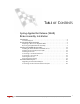
TABLE OF CONTENTS Spring Applied Air Release (SAAR) Brake Assembly Installation Introduction . . . . . . . . . . . . . . . . . . . . . . . . . . . . . . . . . . . . . . . . . . . . . . . . . . . 2 Technical Support . . . . . . . . . . . . . . . . . . . . . . . . . . . . . . . . . . . . . . . . . . . . 2 The Hydraulic Brake Assembly . . . . . . . . . . . . . . . . . . . . . . . . . . . . . . . . . . . . 4 Preparing to Remove the Hydraulic Brake . . . . . . . . . . . . . . . . . . . . . . . . . .
SPRING APPLIED AIR RELEASE (SAAR) BRAKE ASSEMBLY INSTALLATION This document provides instructions for installing the Spring Applied Air Release Brake Assembly (P/N 77010008) as an upgrade to model 224 Automotive Dynamometers (dynos). To ensure safety and accuracy in the procedures, perform the procedures as they are described.
SPRING APPLIED AIR RELEASE (SAAR) BRAKE ASSEMBLY INSTALLATION Introduction INTRODUCTION ................................... The Spring Applied Air Release (SAAR) Brake Assembly (P/N 77010008) may be used to replace the hydraulic brake on model 224 dynamometers. This guide provides instructions for removing the hydraulic brake and installing the SAAR brake assembly. The SAAR brake provides braking to the dyno drum through the use of a spring applied brake mechanism.
SPRING APPLIED AIR RELEASE (SAAR) BRAKE ASSEMBLY INSTALLATION Introduction 77010008 Stock Code 21612112 21612400 21612900 21612901 32904080 32916144 34761003 36582471 61312105 64111005 Spring Applied Brake Upgrade, 224 Description Mount, Air Can, Upgrade, 224 Brake Arm, 24 Brake Shoe Retainer, 224 Brake Actuating Tube, 224 Hairpin Cotter, 7/16"-3/4" Clevis Pin, 1/2" x 4-1/2" Air Canister, Type R30 Bolt, 3/8-16 x 1-1/2", Flange-Hex Brake Holder Weldment, 224 Brake Solenoid Assembly, 224-2 Quantity 1 4 2 1
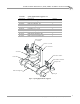
SPRING APPLIED AIR RELEASE (SAAR) BRAKE ASSEMBLY INSTALLATION The Hydraulic Brake Assembly THE HYDRAULIC BRAKE ASSEMBLY ................................... When upgrading to the SAAR Brake Assembly, you will remove the previously installed hydraulic braking system shown in Figure 2. In order to minimize your exposure to the fluid used in the hydraulic brake assembly, you will remove the major portion of the assembly as one piece.
SPRING APPLIED AIR RELEASE (SAAR) BRAKE ASSEMBLY INSTALLATION The Hydraulic Brake Assembly PREPARING TO REMOVE THE HYDRAULIC BRAKE 1 2 3 4 Version 1 Turn off the power and unplug the dyno electronics and observe all applicable safety procedures. Shut off and release the air pressure to the air pressure regulator. Remove covers as necessary to provide yourself good access to the braking components. Refer to your dyno manuals, if necessary, to review removing the covers.
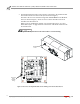
SPRING APPLIED AIR RELEASE (SAAR) BRAKE ASSEMBLY INSTALLATION The Hydraulic Brake Assembly 5 On standard dynos the brake control wiring is connected to the breakout board. The breakout board is located on the dyno as shown in Figure 3. Disconnect the two wires from the wiring block labeled BRAKE on the Breakout board, as shown in Figure 3. These two wires connect the brake solenoid. It should now be disconnected.
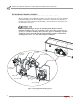
SPRING APPLIED AIR RELEASE (SAAR) BRAKE ASSEMBLY INSTALLATION The Hydraulic Brake Assembly REMOVING THE HYDRAULIC BRAKE ASSEMBLY 1 Remove the four springs holding the brake head pivot pin to the brake frame rail. disconnect air hose or cut air hose close to solenoid BR012 brake head pivot pin brake frame rail remove four springs Figure 4: Remove the Springs 2 Use a large flat blade screw driver or small pry bar to pry the brake shoe retainer out of the brake holder.
SPRING APPLIED AIR RELEASE (SAAR) BRAKE ASSEMBLY INSTALLATION The Hydraulic Brake Assembly 3 Remove the brake shoes from the assembly by sliding them to the outside. Set the brake shoes aside to be reused with the SAAR Brake Assembly. BR015 slide brake shoes toward the outside and remove Figure 6: Remove the Brake Shoes 4 cotter pin Remove the cotter pin from the brake clevis pin on both brakes.
SPRING APPLIED AIR RELEASE (SAAR) BRAKE ASSEMBLY INSTALLATION The Hydraulic Brake Assembly 5 Slide the brake clevis pin into the square recesses provided. The brake clevis pin will only slide in one direction. You may need to slide your brake clevis pin opposite to the direction shown in Figure 8 if your brake clevis pin faces the other way. After you remove the hydraulic brake assembly, you will reach in to remove the pivot pins from inside the square recesses.
SPRING APPLIED AIR RELEASE (SAAR) BRAKE ASSEMBLY INSTALLATION The Hydraulic Brake Assembly 6 Remove four lower bolts holding the slave cylinders and brake head assembly to the brake frame rail. 7 Remove the four bolts holding the master cylinder bracket to the dyno, supporting the hydraulic brake assembly during the final removal of the bolts.
SPRING APPLIED AIR RELEASE (SAAR) BRAKE ASSEMBLY INSTALLATION The Hydraulic Brake Assembly 8 The hydraulic brake assembly should now be completely free. Remove it from the dyno. 9 Extract the brake clevis pins from the square recesses and set them aside. Note: You will reuse the brake shoes and the two clevis pins. The other parts can be appropriately discarded. .
SPRING APPLIED AIR RELEASE (SAAR) BRAKE ASSEMBLY INSTALLATION Installing the SAAR Brake Assembly INSTALLING THE SAAR BRAKE ASSEMBLY ................................... The following instructions are for installing the Spring Applied Air Brake Assembly on a 224 above-ground or pit dyno.
SPRING APPLIED AIR RELEASE (SAAR) BRAKE ASSEMBLY INSTALLATION Installing the SAAR Brake Assembly 3 Insert the brake clevis pin through the holes as shown in Figure 12. 4 Install the hairpin cotter. 5 Use the same method to install the remaining brake weldment with arms, pivot, and hairpin cotter.
SPRING APPLIED AIR RELEASE (SAAR) BRAKE ASSEMBLY INSTALLATION Installing the SAAR Brake Assembly INSTALLING THE AIR CAN MOUNT AND TUBE 1 Install the air can mount using the four 3/8"-16 x 1-1/2" flange bolts provided BR027 four 3/8"-16 x 1-1/2" flange bolts air can mount air can assembly Figure 14: Attach the Air Can Mount to the Dyno 14 Spring Applied Air Release (SAAR) Brake Assembly Installation
SPRING APPLIED AIR RELEASE (SAAR) BRAKE ASSEMBLY INSTALLATION Installing the SAAR Brake Assembly 2 Slide the tube through the brake arms. 3 Rotate the tube so that the center hole is oriented vertically.
SPRING APPLIED AIR RELEASE (SAAR) BRAKE ASSEMBLY INSTALLATION Installing the SAAR Brake Assembly INSTALLING THE AIR CAN 1 2 Thread the pipe fitting which extends from the solenoid subassembly into the threaded hole on the top of the air can. Apply pipe thread sealer to the fitting if sealer is not already present. Align the solenoid assembly so that it is parallel to the two bolts that extend from the bottom of the air can as shown in Figure 17.
SPRING APPLIED AIR RELEASE (SAAR) BRAKE ASSEMBLY INSTALLATION Installing the SAAR Brake Assembly 5 While lowering the air can through the hole in the tube, align the air can studs with the holes in the bracket. Note: The rod will not extend all of the way through the tube until the electronics are connected and air pressure is applied to the air can. 6 Loosely attach the air can to the bracket using the two 5/8" nuts and lockwashers removed earlier.
SPRING APPLIED AIR RELEASE (SAAR) BRAKE ASSEMBLY INSTALLATION Installing the SAAR Brake Assembly CONNECTING TO THE BREAKOUT BOARD 1 2 Connect the two black wires from the solenoid to the two terminals on the breakout board labelled BRAKE (one to each terminal). If you have a 4 wheel drive dyno model 224-248 or 224-224, refer to additional instructions for “Four Wheel Drive Dynos” on page 20.
SPRING APPLIED AIR RELEASE (SAAR) BRAKE ASSEMBLY INSTALLATION Installing the SAAR Brake Assembly FASTENING THE AIR CAN 1 2 Check to make sure that the area is clear and that the dyno can be operated safely. Power up the dyno electronics. Keep hands and fingers clear when operating dyno. 3 4 5 6 7 8 Use the pendant to turn the brake to the OFF position.
SPRING APPLIED AIR RELEASE (SAAR) BRAKE ASSEMBLY INSTALLATION Four Wheel Drive Dynos FOUR WHEEL DRIVE DYNOS ................................... The instructions in the following sections describe the differences for installing the SAAR Brake Assembly on four-wheel drive dynos. The SAAR Brake Assembly may be used to upgrade the braking on 224-248 model and 224-224 four-wheel drive dynos. The 224-248 dyno has a stationary 248 dyno and a moveable 224 dyno.
SPRING APPLIED AIR RELEASE (SAAR) BRAKE ASSEMBLY INSTALLATION Four Wheel Drive Dynos control box connect the two black wires from the brake solenoid to the terminals labelled BRK 2 on movement board connect air hose to solenoid, replace hose if needed BR033 RAIL OUT IN BRK 2 BRK 1 BRK IN +12V GNDCOM IN OUT -- PRES SW movement board Figure 22: Connect from Solenoid to the Movement Board in the Control Box Version 1 Spring Applied Air Release (SAAR) Brake Assembly Installation 21