
Installation Guide Owner manual


EFIS-D10A Installation Guide 3-1
3. INSTRUMENT INSTALLATION
This section provides you with the information needed to physically and electrically install the
EFIS-D10A.
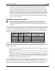
Selecting a Remote Compass Module Location
Finding a good location for the EDC-D10A
remote compass module is critical to an
accurate EFIS-D10A heading display. Keep
in mind that calibration can compensate for
small static magnetic fields superimposed
upon the earth’s field; it cannot take
into account dynamic effects like
AC currents, non-constant DC
currents and non-stationary ferrous
material (e.g., an electric turn
coordinator). Use the following
suggestions to help you find a good
location for your EDC-D10A.
Keep the EDC-D10A away
from any source of magnetic fields (such
as electrical equipment and current-
carrying wires) and ferrous material.
e
Move a handheld compass throughout the
space surrounding your location to get a
rough idea of the suitability of your
chosen location. If the needle deviates
significantly from magnetic north in any
given area, that location would not be
ideal for the EDC-D10A.
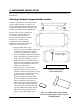
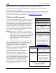
The EDC-D10A can be mo unted
anywhere in the aircraft (away from
magnetic interference) such that its pitch
is as close to that of the EFIS-D10A as
possible. It does not need to be
directly along any axis of the EFIS-
D10A. It should be mounted with the
long axis parallel to the wings, the
electrical connector facing toward the
front of the plane, and the mounting
tabs on the bottom. The bracket used
to hold the EDC-D10A must hold th
EDC-D10A at the same pitch, roll,
and yaw as the EFIS-D10A with
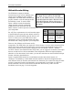
Connector forward and
tabs mounted down
Connector toward
direction of flight
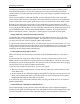
Side view of EDC-D10A, tabs mounted
down and aligned within 1 degree of pitch
with EFIS-D10A