
Installation Guide User Manual


Wiring Overview
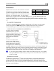
+5V Excitation
Some of the sensors require either a direct connection, or
connection via a resistor, to the +5V excitation circuit. We
recommend that you allow for more than one splice into
this line.
Pin Color Function
18 White/red
+5V
excitation
Thermocouple Harness Preparation
Refer to the 25-Pin Male EMS Harness section on page 2-5 during this procedure. Strip 1” of
brown outer insulation off each thermocouple wire pair on the supplied 25-pin thermocouple
harness. Strip ¼” of insulation from each of the thermocouple wires inside. Crimp the supplied
male Fastons onto each wire on the thermocouple harness. These will later be inserted into the
female Fastons on each thermocouple.
Do not connect the Fastons on the harness with those on the thermocouples until you have routed
the wires and mounted the thermocouples at the desired location.
The thermocouple wires can be cut to a desired length if your application requires. If you need to
extend the length of the thermocouple, you must use the correct type (J or K) thermocouple wire
to accomplish this. It is acceptable to use non-thermocouple fasteners to join two pieces of
thermocouple pair wire, provided the junction does not extend very far or have large temperature
differences across it. Please contact Dynon Avionics to order extension wire.
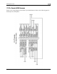
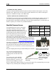
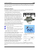
Harness Mating
The following diagram shows the 2 electrical connectors on the back of the EMS-D120. The
main EMS harness (for all connections except EGT & CHT thermocouples) should terminate in
a 37-pin female D-sub connector. The EGT/CHT thermocouple harness should terminate in a 25-
pin male D-sub connector. The following pages provide wiring diagrams and details for each of
these harnesses.
EMS-D120 Installation Guide 2-3