
Installation Guide User Manual

Transducer Installation
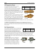
Fuel Flow Sensor
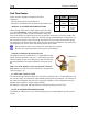
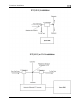
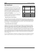
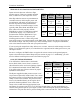
Pin Color Function
Dynon Avionics supplies two different fuel flow
transducers:
13 Black Ground
Yellow (or
white)
Fuel flow
input
EMS-D120 Installation Guide 3-9
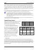
¼” NPT Female
Floscan 201B (Dynon P/N 100403-001)
Electronics International FT-60 (Dynon P/N 100403-003)
GENERAL PLACEMENT RECOMMENDATIONS
14
15 Red
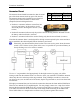
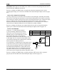
When placing either sensor, ensure that the three wire leads
are pointed straight up. A filter should be placed upstream
from the sensor to screen out debris. Placement of the fuel
flow sender relative to other items in the fuel system like fuel pumps is left to the builder. The
manufacturer of the fuel flow sender does not make strong recommendations on this point. It is
not uncommon, though, to place the sender downstream of any auxiliary electric boost pumps
but upstream of the engine driven fuel pump. For best measuring performance, the fuel should
travel uphill by one to two inches after leaving the fuel flow sender.
Fuel flow
power
(14V)
Due to vibration issues, never connect the sensor directly to engine.
Do NOT use Teflon tape when screwing in any of the fittings.
FLOSCAN TRANSDUCER INSTALLATION
The FloScan fuel flow transducer has ¼” female NPT threads
at both the inlet and outlet. Only use ¼” NPT fittings to match.
When installing, do not screw fittings more than two full turns
past hand tightened. The torque should not exceed 180 inch-
lbs.
Make note of the numbers on the tag attached to the fuel
flow sensor. You will need it in the Fuel Flow Configuration
section on page 5-14.
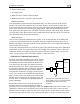
EI “RED CUBE” INSTALLATION
The Electronics International “Red Cube” FT-60 flow transducer has ¼” female NPT ports. Do
not exceed a torque of 300 inch-lbs when installing fittings into the transducer. The fuel line on
the outlet port should not drop down after exiting the transducer. This configuration can trap
bubbles in the transducer, causing jumpy readings.
The inlet port, outlet port, and flow direction are marked on the top of the FT-60.
ROTAX PLACEMENT RECOMMENDATIONS
If installing on a Rotax 912, review the following page for recommendations specific to these
engines.