
Installation Guide User Manual


Transducer Installation
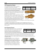
Next, crimp the two supplied #8 ring terminals onto the wires using the fusing method chosen
above. Connect the other ends of the fuses to the Amps High and Amps Low leads (pins 24 and
25) on the 37 pin harness. Unscrew the two smaller screws on the ammeter shunt. Slide the ring
terminals onto them and screw them back into the base. The “Amps High” lead should be located
on the side of the shunt which is closest to the battery, or in the case of position B, closest to the
alternator.
If you find that the current reading on the EMS-D120 is the opposite polarity of what you want,
swap the two signal inputs (Amps High and Amps Low) to obtain the desired result.
It is extremely important that you secure all loose wires and ensure that exposed
terminals cannot touch or short out to other objects in the plane. All metal on the shunt is
at the same voltage as – and carries the same risks as – the positive terminal on the
battery. Improperly installing the ammeter shunt can result in high current flow, electrical
system failure, or fire.
If you are using GRT’s Hall effect amps transducer (P/N CS-01), route its output to pin 24, the
Amps High input, on the 37-pin EMS connector.
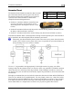
General Purpose Inputs
Dynon Avionics supports many sensors for which the
EMS-D120 does not have dedicated inputs. The
instrument has 3 GP (general-purpose) inputs which
can be used for a variety of sources.
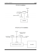
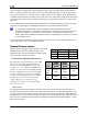
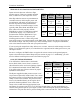
OUTSIDE AIR TEMPERATURE SENSOR
Pin Color Function
4 Purple/blue GP 1
22 Purple/yellow GP 2
23 Purple/green GP 3
Note that this section only applies to the OAT
with 2 wires (both colored black/white), for
connection to the EMS DB37 connector. If
you have the 3-wire OAT and an EFIS-based
product, see that product’s Installation Guide
for more information on connecting the OAT
to that product. If you do not have an EFIS
product, you may still use the 3-wire OAT, by
ignoring the red wire and connecting the
yellow and blue wires (irrespective of
polarity) in the same way as the black/white
wires described here.
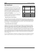
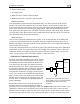
EMS
harness
Color
OAT
sensor
color
Pin Function
Desired
GP
input #
Black/
See chart
above
GP
White
Black/
Ground
pin
Black
White
ground
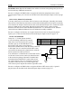
Mount Location
It is important that the OAT probe be mounted somewhere on the skin of the aircraft where it
will not be affected by heat sources (sun, engine, aircraft interior, etc). The ideal location would
receive no heat from the aircraft engine or any other source in the aircraft body. While this may
be impractical, it is a good idea to mount the probe as far away from heat sources as possible. On
the RV series, common locations include the wingtip and under the horizontal stabilizer. Avoid
these three locations:
EMS-D120 Installation Guide 3-13