
Installation Guide User Manual

Transducer Installation
TRIM AND FLAPS POSITION POTENTIOMETERS
Dynon Avionics does not sell trim or flaps
position sensors. These are normally included
with, or added on to, their respective servos.
Most flap and trim sensors are potentiometers
(variable resistors) which require power and
ground inputs, and supply an output that is a
function of position. These potentiometers
come in a variety of resistance ranges, but are
typically 1kΩ, 5kΩ, 10kΩ, and 20kΩ. All of
these values will work properly with the
EMS-D120, as there is a calibration required,
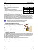
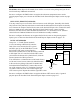
as described on page 5-6. Connect the 5V
Excitation line from the EMS-D120 37-pin
EMS connector to the +5V input on your
trim/flap position sensor. Connect the ground
input on the sensor to a ground common to the EMS-D120. Connect the output of the sensor to
the desired GP input. You may connect up to three trim/flap sensors. For physical installation,
refer to the instructions that came with your position sensor.
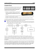
If you are using the output from a Ray Allen servo or sensor, connect its white/orange wire to the
Dynon 5V excitation line (pin 18), its white/blue wire to ground, and its white/green wire to your
GP input of choice.
Be sure to configure the EMS-D120 to recognize the various sensors on the general-purpose
inputs as described in the General Purpose Inputs section on page 5-17. Additionally, you will
need to calibrate each flap/trim sensor as described on page 5-6.
DB37
EMS
Pin
EMS
harness
Color
Position
Pot
Function Function
Desired
GP
input #
See chart
on page 3-
13
Position
out
(voltage)
GP
18 White/Red +5V in
Position
sensor
power
Ground
pin
Black
3-16 EMS-D120 Installation Guide
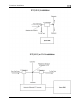
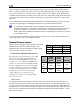
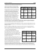
COOLANT PRESSURE SENSOR
You will find two 1kΩ resistors (color bands:
brown, black, black, brown, brown; connect in
either direction) in the accessories package (Dynon
P/N 100446-000) included with the EMS-D120.
You will be using one of these resistors for proper
installation of this sensor.
Ground in
(common
to EMS)
ground
DB37
EMS Pin
EMS harness
Color
Function
Desired
GP input
#
See chart on
page 3-13
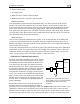
The Dynon-supplied coolant pressure sensor is a 0-
30 psi sensor (Dynon P/N 100411-000). First, mount
the pressure sensor to a fixed location using an Adel
clam
p or other secure method. The pressure sensor
must not be installed directly to the engine due to
potential vibration problems. Next, connect the
sensor to the coolant line using appropriate hoses
and fittings. Its pressure port has a 1/8-27 NPT pipe thread fitting; you may need adapters to
connect to the pressure port on your engine. Locate (or drill and tap) the pressure port along the
coolant line. This port must have a pressure fitting with a restrictor hole in it. This restrictor hole
GP
18 White/Red
5V supply
to 1kΩ
resistor
Ground
pin
Black
Ground in
(common
to EMS)