
Installation Guide User Manual


EMS Configuration
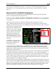
Once you are ready to calibrate, select the desired trim that you would like to calibrate, and press
SEL► to enter its calibration menu. Press the RANGE button to begin calibrating the range of
the trim. Follow the onscreen instructions, controlling trim to the required position before
pressing NEXT. Repeat the process for the opposite position. The process will then prompt you
to put the trim into takeoff position. If you do not require a takeoff indication on the given axis’
trim display, you may press NONE. When you have completed the calibration, press the DONE
button.
Press the TAKOFF button to calibrate the takeoff position indicator. When calibrated, a green
line is displayed on the trim scales, indicating takeoff position.
View the trim display on the EMS Main or Aux page (depending on where you configured it to
display) to make sure that it works as expected. You may repeat this calibration process as many
times as you wish.
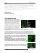
Flaps Calibration
Prior to calibrating your flaps sensor, ensure that you have connected it as
described on page 3-15 and selected FLAP POS for the desired GP input FUNCT
parameter as described on page 5-17.
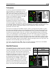
Enter the EMS menu by pressing any button below an EMS main page and
pressing MORE > SETUP > MORE > FLAPS. The FLAP CALIBRATION menu
just shows FLAPS, followed by the GP input that each is configured as (or NONE,
if no GP input is configured for a given axis). Ensure that this list corresponds to
the physical connections made during the setup described in the section. Press
SEL► to enter the flaps calibration menu.
During the calibration process, ensure that the number shown in the VALUE field changes as
you adjust the flaps. If the number does not change, the flaps sensor may be incorrectly wired to
the EMS-D120, or incorrectly configured in the GP input selection under the SENSOR menu. At
any point in the process, you may press CANCEL to end the calibration without overwriting the
previous calibration results.
You must calibrate for at least 2 positions, and may calibrate for as many as 5. The calibration
process first requires you to put the flaps in the 0° extended position. When you have done this,
press NEXT. Next, you will calibrate for the second position. Press INC+ or DEC- to set the
angle that you would like displayed for the second position. If you only wish to have 2 positions
displayed, press DONE. Otherwise, press NEXT to repeat the process for the third position.
When you have completed the calibration, press DONE. View the flaps display on the EMS
Main or Aux page (depending on where you configured it to display) to make sure that it works
as expected. You may repeat this calibration process as many times as you wish.
EMS-D120 Installation Guide 5-7