
Installation Guide User Manual


2. WIRING OVERVIEW
Please follow these instructions explicitly as improper wiring can result in permanent damage to
your instrument and/or the accompanying sensors.
All electrical power and data lines interface with the EMS-D120 via the male 37-pin D-Sub
connector on the back of the unit. EGT (exhaust gas temperature) and CHT (cylinder head
temperature) thermocouple inputs enter the unit via the female 25-pin D-Sub connector. You
should ensure that all electrical connections are tested and properly working before completing
the final physical assembly.
Recommended Wiring Practices
For all electrical connections, use correct wiring techniques, taking care to properly
insulate any exposed wire. A short circuit between any of the wires may cause damage to
the EMS-D120 and/or your aircraft. Make all connections to your harness before
plugging it into any of the components of the system. Do not make connections while
power is applied at any point in the system.
Dynon Avionics sells wiring harnesses for all connections to the EMS-D120. The harnesses are
made up of 22 AWG wire and – with the exception of the thermocouple harnesses – meet Mil
Standard MIL-W-22759/16 (Tefzel insulation). If you have opted not to purchase these
harnesses, please refer to the provided wiring diagrams for construction information. We
recommend that all wire you use also meets Mil Standard MIL-W-22759/16; all wire supplied by
Dynon Avionics (with the exception of thermocouple wire, which uses FEP insulation) meets
this specification.
When using any pre-manufactured harness, verify that each pin has continuity with the expected
wire on the wiring diagram. This test can be easily done with a multimeter. When verifying
harnesses, use the wiring charts and diagrams in this guide as your ultimate authority on pin
function (for any harness) and wire color (for harnesses purchased from Dynon Avionics).
Route all wiring through the engine compartment such that there are no spots where it could
chafe or break. Use appropriate strain relief at all junctions between wires and connectors. We
recommend that you secure all wires at regular intervals along wiring runs to accommodate
vibration effects.
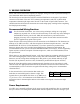
In the sections below, each connection that needs to be
made has an associated legend, as shown at right. This
legend refers to pin numbers and colors on the EMS female
37-pin harness only. All connections on the EMS male 25-
pin harness route to thermocouples and are color-coded to correspond to the thermocouple
coloring.
Pin Color Function
# Color function
Power Requirements
22 AWG wire is normally sufficient for the power supply and ground lines, but we recommend
that you consult a wire sizing chart and determine the size required for the wire routing in your
EMS-D120 Installation Guide 2-1