
Installation Guide Instruction Manual


Wiring Overview
fuse for the wire you select. Power is fed to the FlightDEK-D180 via pins in the female D-25
connector as shown on the 25-Pin Female EFIS Harness diagram on page 2-4.
The FlightDEK-D180 system-wide power requirement is 14 watts typical and 19 watts
maximum. On a 12-volt system, this translates to about 1.5 amps of maximum current draw. On
a 24-volt system, this translates to about 0.8 amps maximum current draw. Normally, a 3-amp
circuit breaker or fuse is sufficient.
Grounding
Many of the engine sensors require a connection to a
shared electrical ground with the FlightDEK-D180. There
are many places on an aircraft where you could connect
these sensors. However, the ideal location to ground these
sensors is near the FlightDEK-D180 to minimize voltage
differences between the sensor and instrument grounds.
Some sensors (e.g., oil pressure and oil temperature)
connect to ground via their cases’ contact with the engine
or aircraft body. There must be a solid connection between
this “case ground” and the FlightDEK-D180 ground. The oil temperature sensor is very
susceptible to voltage differences between the engine case and the negative terminal of the
battery. Ensure that solid, thick electrical connections exist between the engine and battery
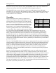
ground. Other sensors (e.g., fuel pressure) do not have a grounded case and have two leads
instead. One lead must be connected to ground, the other to the sensing input of the FlightDEK-
D180. The FlightDEK-D180 has 3 pins on the 37-pin harness which may be used for connecting
such sensors to ground. More than one sensor’s ground may be connected to any of these three
grounds using a splice.
EMS
DB37
Pin
Color Function
5 Black Ground
16 Black Ground
17 Black Ground
The case of the FlightDEK-D180 is connected to its supply ground. If your panel is connected to
aircraft ground, the connection between the instrument’s case and the panel dramatically helps
minimize voltage differences between the instrument and sensor grounds. If your panel is not
metal, or is otherwise isolated from engine ground, connect a 14 AWG or larger wire to the
instrument case. The most convenient place to do this is at the back of the mounting tray.
Additionally, connect any unused EMS ground leads to a convenient ground. Keep all ground
leads as short as possible.
Because of the current drawn by the FlightDEK-D180, even very small resistances between
battery ground and instrument ground can cause voltage differences which adversely affect
engine sensor readings. An easy way to test the quality of the instrument’s ground is to measure
voltage between the ground pin at the FlightDEK-D180 and the ground lead at your aircraft’s
battery. With the FlightDEK-D180 powered on, connect one lead of your voltmeter to a free
ground lead coming from the FlightDEK-D180. Connect the other lead of your voltmeter to the
ground terminal of your battery. The voltage between these two points should measure very
close to 0 mV (within 5 mV). If it does not, you must improve the ground connection between
the ground of your battery and that of your avionics bus.
2-2 FlightDEK-D180 Installation Guide