
Installation Guide Instruction Manual


Autopilot Installation and Configuration
Repeat the AP-commanded climbs/descents and torque adjustments until the ALT indicator does
not display a slip indication.
Continue performing AP-commanded climbs and descents, and observe the overall behavior of
the aircraft. If the aircraft oscillates in holds or overshoots as it reaches target altitude, that is an
indication that the Pitch Servo SENSITIVITY needs to be increased. If, upon reaching the target
altitude the stick “twitches” excessively, that is an indication that the Roll Servo SENSITIVITY
needs to be decreased.
You should be able to find a SENSITIVITY value that is acceptable for altitude holds,
climbs, and descents in smooth air. You may, however, find that in periods of extended
turbulence, a lower SENSITIVITY value must be set.
Step 9h – Verify AIRSP MIN/MAX, and VSPD MAX settings during altitude changes
During an AP-commanded climb, verify that the time to complete the climb matches your
expectations given the setting for the VSPD MAX parameter. For example, when VSPD MAX is
set to 500 ft/min, a 500-foot climb should take about 1 minute. If this is not the case, the climb
rate may be limited by the AIRSP MIN parameter, and the ADD POWER message is displayed.
Likewise, during an AP-commanded descent, verify that the time to complete the descent
matches your expectations given the setting for the VSPD MAX parameter. If it does not, the
descent rate may be limited by the AIRSP MAX parameter, and the DECREASE POWER
message is displayed.
If necessary, adjust the AIRSP MIN, AIRSP MAX, and VSPD MAX parameters as described
above.
At this point, all the parameters in the AP > PITCH SERVO menu are properly tuned.
Step 9i – Execute several AP-controlled changes of altitude and observe the overall aircraft
performance.
There may be some interaction between Pitch Servo Torque and Pitch Servo Sensitivity settings.
Repeat the above steps as necessary to achieve acceptably smooth overall AP response during
altitude holds and changes.
Step 9j – Observe and verify trim indications during altitude holds and changes
Find an area with a lot of clearance above and below the aircraft’s altitude. With the AP
disengaged, put the aircraft into neutral trim. Engage the AP in ALT mode (and HDG or TRK
mode if desired) and allow the AP to maintain altitude (and heading, if engaged). Trim the
aircraft nose down; the AP will maintain the target altitude, despite
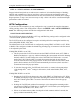
the nose down trim. Continue trimming nose down
just until a
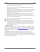
yellow UP▲ indicator displays (and stays on) next to the AP status
indicator at the lower left of the EFIS screen (shown at right). This
indicator displays when the AP senses too much nose down trim. Trim the aircraft nose up until
the indicator disappears. Disengage the AP to observe the state of the aircraft’s trim.
Repeat the above procedure, trimm
ing the aircraft nose up until the yellow DN▼ indicator
displays (and stays on). Then, trim nose down until the indicator disappears.
During turbulence and small bumps the trim indicator may flash on and off. Do not take action
based on the trim indicator until it remains on for several seconds.
FlightDEK-D180 Installation Guide 8-29