
Installation Guide Instruction Manual


Appendix
FlightDEK-D180 Installation Guide 9-7
Appendix B: Dynon EFIS OAT Probe Installation and Usage
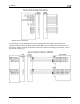
Note that this section only applies to the OAT with 3 wires (colored red, yellow, and blue), for
connection to the EDC-D10A. If you have the 2-wire EMS OAT connected to the DB37
connector, you do not need to also have the EFIS OAT connected. See the Outside Air
Temperature Sensor installation section on page 3-13 for information on installing the 2-wire
OAT. Ensur
e that no EMS GP input is configured as an OAT. Only one type of OAT can be
connected to the system.
The following instructions provide information on installing and using the FlightDEK-D180
OAT probe. Keep in mind that this probe is designed specifically to work with Dynon products.
Do not expect it to work properly with another OAT or TAS/Density Altitude system. Your
FlightDEK-D180 can receive its OAT value from the 2-wire EMS OAT; it is not necessary to
use both OATs.
TOOLS AND MATERIALS REQUIRED
Dynon Avionics OAT probe/cable with nylon nut and washer.
Drill with 3/8” bit
Dynon Avionics EDC-D10A remote compass module.
2 machined D-sub pins
D-sub pin crimp tool
Loctite
INSTALLATION
Mount Location
It is important that the OAT probe be mounted somewhere on the skin of the aircraft where it
will not be affected by heat sources (sun, engine, aircraft interior, etc). The ideal location would
receive no heat from the aircraft engine or any other source in the aircraft body. While this may
be impractical, it is a good idea to mount the probe as far away from heat sources as possible. On
the RV series, common locations include the wingtip and under the horizontal stabilizer. Avoid
these three locations:
Engine exhaust paths
The engine itself
Where the sensor will have direct sunlight
Where the backside is exposed to a heated cabin
Mounting Instructions
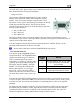
After the mounting location has been determined, drill a 3/8” hole in the skin at the desired
location. Uncoil the cable attached to the OAT probe. Remove the nylon nut from the cable.
From outside the skin of the aircraft, insert the cable first and then the threaded end of the OAT
probe. From within the skin of the aircraft, gently pull the cable until the threaded end of the
OAT probe pokes through the hole. Thread the nylon nut down the cable and up to the threaded