
Installation Guide Instruction Manual


AppendixAppendix
PANEL LOCATION AND MOUNTING
This section provides you with dimensions, panel location, and mounting information.
HS34 Dimensions and Panel Location
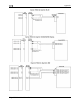
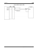
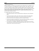
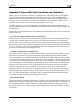
The diagram below shows the HS34’s outer dimensions. Note that the instrument extends about
3.7” behind the panel, and that harnesses can require up to three more inches. Use the
dimensions (in inches) found on the diagram to plan for the space required by the instrument.
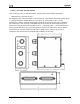
The front bezel of the vertically oriented HS34 (100755-000) is the same height as Dynon’s
D100-series products and can be mounted close to – or abutted against – one if desired. Plan a
panel location that allows for convenient operation of the knobs and buttons. Ensure that the
instrument is in a location where the light sensor (small circle of rubber at upper left of
instrument) can measure the true ambient light conditions in the cabin.
FlightDEK-D180 Installation Guide 9-17 FlightDEK-D180 Installation Guide 9-17