
Installation Guide Instruction Manual


Appendix
HS34 CONFIGURATION
This section guides you through configuring your HS34. Prior to beginning this section, you
must have completed all the steps in the DSAB Configuration chapter with the HS34 turned on
and connected to the DS
AB network. After DSAB configuration, ensure that the HS34 appears
as one of the ACTIVE devices in the EFIS > SETUP > DSAB > STATUS menu.
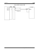
You may only configure your HS34 on the EFIS-based instrume
Master role. The following configuration steps are performed within th
menu on the Bus Master instrument.
Device Communication Setup
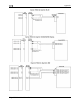
If you have connected a NAV radio to the analog
diagram
on page 9-13, enter the ANALOG menu to configure comm
Press SEL► to change the INPUT ENABLED to Y. The SYNC
H OFFSET parameter is used to
correct analog errors that can occur in the signal path between your radio and the HS34’s
measurement. You may normally leave SYNCH OFFSET set to 0. However, if you observe
errors in the green course pointer on the HSI Page, you – or a qualified avionics shop – may
modify this parameter to bring the course pointer into agreement with the NAV radio. Set
SYNCH OFFSET, in degrees, to a value equal to the number of degrees of error in the course
pointer on the HSI Page.
If you have connected one or two devices outputting
serial d
nn
ate us
d ba
one or two devices outputting
,
at t
ev
co
UT
t
nt assigned the DSAB Bus
e EFIS > SETUP > HSI
pins shown in the Analog Connections
unication with this device.
ata, push DOWN▼ to select the
cted to the SERIAL 1 RX and TX pins
ending on the output format configured
ected to the serial pins is a Garmin
L30 CMD.
ed by your SL30 or GPS. Many
ud rate; ensure that the INPUT and
gs in the communication setup for the
a second NAV radio or GPS connected
ARINC-429 data, push DOWN▼ to select
T1 to the type of device connected to the
GAMA NAV, or DME. If you have
he above configuration for the
t set the SPEED parameter (HIGH or
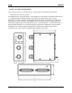
ices. The HS34 has one ARINC output
nvenience. If one or both of your
DATA to ON and configure OUTPUT
products connected to a DSAB system
be connected to the HS34.
SERIAL m
enu, and SEL► to enter it. If the device conne
is a GPS, set INPUT to either AVIATION or NMEA (dep
on your GPS), and OUTPUT to NONE. If the device co
SL30 Nav/Comm, set INPUT to SL30 and OUTPUT to S
Set the BAUD RATE parameter to match the baud r
devices support more than one type of data format an
BAUD RATE settings for SERIAL 1 agree with the settin
device connected to the HS34’s Serial 1 pins. If you have
to the Serial 2 pins, repeat the above steps for it.
If you have connected
the ARINC-429 m
enu, and SEL► to enter it. Set INPU
HS34’s ARINC-429 RX 1 A and B inputs: GAMA GPS
connected a device to ARINC-429 RX 2 A and B, repe
INPUT2 parameter; otherwise, leave it set to NONE. Nex
LOW), based on the output speed of your two ARINC d
channel with 2 sets of pins on the connector for wiring
ARINC devices can accept commands, set the OUTP
SPEED appropriately.
Note that the EFIS/EMS SERIAL menu is disabled on all
with an HS34 connected. All GPS and NAV devices mus
FlightDEK-D180 Installation Guide 9-19