
Installation Guide Instruction Manual


Appendix
TOOLS AND MATERIALS REQUIRED
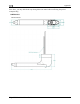
Dynon Avionics AOA/Pitot probe.
Two plumbing lines (usually ¼” soft aluminum or plastic tubing) routed from the
FlightDEK-D180 to the probe mounting location.
Tubing interface hardware
o Reference our wiki at wiki.dynonavionics.com for tubing interface hardware
ounting bracket. Models known to work well include:
aero.com/mountbracket.html
recommendations.
#36 Drill and 6-32 tap
AOA Pitot M
o Gretz Aero CBK12 (Chrome) and PBK12 (Paintable), available at
gretz
or from Aircraft Spruce.
d lip for the RV series. It is available
o SafeAir1 also makes a bracket with a joggle
from www.safeair1.com
.
Please follow these instructions explicitly as improper installation can result in permanent
damage to your device and/or aircraft.
HEATER CONTROLLER WIRING AND MOUNTING
If you have purchased the heated version of the probe, please follow the instructions in this
s rsion of the probe, you may skip to the AOA/Pitot
P ollow these instructions explicitly as improper
th
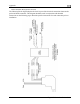
end the
re the heater controller
via the 4 mounting holes. Route the
wiring between the probe, controller, panel, and power source, as described below.
ection. If you have purchased the unheated ve
robe Mounting section on page 9-28. Please f
installation can result in perm
anent damage to your device and/or aircraft.
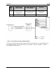
Heater Controller Mounting
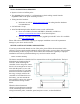
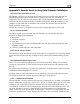
The heater controller box should ideally be mounted close to the AOA/Pitot Probe. The box’s
dimensions are found at right, for
reference. When mounting the
controller close to the probe, ensure
that it is close enough for its wires to
m
ate with the probe’s wires, with
room for strain-relief. If you find it
difficult to mount the controller in
the wing, or simply wish for the
controller to be mounted closer to
e battery, you must ext
lines using the correct wire gauge as
described in the Wiring section
below.
When the desired location is
selected, secu
FlightDEK-D180 Installation Guide 9-25