
Installation Guide Instruction Manual


Appendix
FlightDEK-D180 Installation Guide 9-27
Heater Controller Wiring
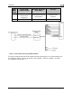
Before making the connections to your Heated
AOA/Pitot Probe and controller, refer to the
Recommended Wiring Practices section on page
2-1. The chart at right provides general
recomm
endations for wire gauge choice, given
wiring run length.
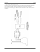
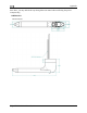
Probe to Controller Wiring
As mentioned above, it is preferable that the
heater controller box be mounted near enough to
the probe that 5 wires between the controller and
probe can be connected without extension. The
three mating pairs of colored wires – terminated with Fastons – are used to carry the current to
the heating element in the probe. The 2 white wires are for temperature measurement, and can
thus be small. If you have mounted the heater controller near the probe and do not need to extend
the wires between the two, simply plug each wire on the controller into its corresponding like-
colored wire from the probe.
If you do need to extend the wires between the probe and the controller, use the recommended
wire size (see chart on page 9-25) for your run length. Since extending the wire runs requires that
you cut the connectors off the 5 wires between the probe and controller, splice the extension
wires between the probe and controller using butt splices or other sim
ilarly secure method. The
white wires are not polarity-dependant. Additionally, as the white wires do not carry any
significant current, you may extend them with 26 AWG or larger for any run length.
Controller Power wiring
Three wires – colored red, black, and white
– exit the controller for connection to your
electrical system. Power (between 10 and
15 volts) is fed to the controller via the red
and black wires. The maximum current
draw of the heated pitot controller/probe is
10 amps. You must route your own
appropriately-sized wires to where the
heater controller is mounted. Both power
and ground lines should be able to handle
10 amps with minimal voltage drop, as
recommended in the chart on page 9-25.
The red wire should be connected through
a pilo
t-accessible switch to the main power
source in the aircraft (limited to 15 volts).
The switch allows you to manually turn the
heater controller on and off, depending on
the situation. Install a 15-amp fuse at any
point along the power line to the heater
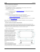
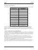
Recommended wire gauge for runs,
given 10-amp peak current
Run length Gauge
0’ – 7’ 18 AWG
7’ – 9’ 16 AWG
10’ – 16’ 14 AWG
17’ – 24’ 12 AWG
25’ – 40’ 10 AWG
From FAA AC 43.13-1B, page 11-30
Color Notes
Red Connected through a pilot-accessible
switch to 10–15V supply. Must handle
up to 10 amps.
Black Must have a constant connection to
ground. This is required for the warning
light to operate when controller is
powered off or not functioning. Line
must handle up to 10 amps.
White Connected to a light bulb (or resistor &
LED) tied to switched ship’s power.
This line is grounded when the heater
controller is powered off or not
functioning. Connection can handle no
more than 1 amp. Current depends on
light source connected.