
Installation Guide Instruction Manual


Appendix
con even when the controller is powered on, it only heats the probe the
ted to gr
the black
ater functions properly whether or not yo
his connection. It is simply
a status output for your convenience.
n the probe he ed off or no g
on the pa other termi
ater is on ite
ed o
priate current to the LED, and can accommodate the power
AOA/PITOT PROBE MOUNTING
The Dynon Avionics AOA/Pitot probe has been designed as an under-wing pitot. The following
n. If you wish to mount your pitot on nose boom
pria tments to your pitot. The heated version
e in mo
func
elatively un d
inches below the
g edge of the win
imize the effect
hown that the or
also w r
ined, mount the d
either case, m
during level f
acket. Use caution when drilling the holes, ensuring
OA pressure lines. As long as you do not penetrate
troller. Remember that
am
ount necessary to maintain temperature.
The black wire should be permanently connec
controller should occur via the red power line, not
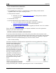
Heater Status Connection
Note: The probe he
ound. Cutting power to the heater
ground line.
u m
ake t
The white heater status wire is grounded whe
properly. This wire should be connected to a light
connected to switched aircraft power. When the he
heater status line is open, leaving the indicator light turn
heater controller – or it is not functioning properly – the white line is grounded, turning the
indicator light on.
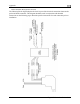
Aircraft Spruce P/N 17-410 is an example of a light that will work for this application. An LED
and resistor in series will also suffice. If you use an LED as the indicator, you must choose a
resistor that delivers the appro
ater is turn t functionin
nel, whose nal is
and functioning properly, the wh
ff. When there is no power to the
required for its current and voltage drop.
If you own a Dynon EMS-based product, you may also use one of its two contact input to
display an onscreen indication. Connect this heater status output directly to the desired EMS
contact input, with no additional resistors or lights. You must configure the contact display as
described in your EMS-based product’s Installation Guide.
inform
ation applies to this type of installatio
mount, contact us so we can make the appro
of Dynon’s AOA/Pitot Probe does not com
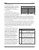
AOA/Pitot Probe Mount Location
The Dynon Avionics AOA/Pitot probe only
where the airflow over the probe is r
recommend that you mount it at least 6
between 2 and 12 inches behind the leadin
mounted about mid-wing span wise to min
tips. Testing during the probe development has s
the pitot probe in the RV series of aircraft
te adjus
a -boom unt configuration.
tions correctly when mounted in a location
disturbe by the aircraft
. In general, we
wing and with the tip of the probe
g. Typically, pitot probes are
s of both the propeller and the wing
standard mounting locations f
orks fo the Dynon probe.
pitot m
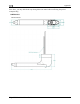
ounting kit per the include
ount the probe securely to the wing
light. Drill and tap mounting holes (#6-
AOA/Pitot Probe Mounting Instructions
After the mounting location has been determ
instructions or fabricate your own mount. In
such that the body of the probe is horizontal
32) on the probe to match your mounting br
that you avoid drilling into the pitot and A
9-28 FlightDEK-D180 Installation Guide