
Installation Guide Instruction Manual


Appendix
FlightDEK-D180 Installation Guide 9-33
directly to your switched avionics power. Ensure that all avionics power is off before performi
this in
ng
the wiring step of stallation.
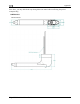
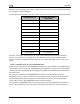
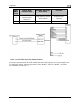
If trobe signal or a D4 pin, leave these pins unconnected. your Altitude Transponder has either a s
Transponder Pin Encoder Converter
Wire Color
A1 Yellow
A2 Green
A4 White with Blue
B1 Blue
B2 Orange
B4 White with Red
C1 White with Green
C2 White
C4 White with Black
Power (10V-30V) Red
Gnd Black
Strobe Signal No Connection
The Gray code output of the Encoder Converter reports altitude not adjusted for barometric
pressure, as required by FAA specification. The altitude reported by the FlightDEK-D180
encoder will always m the BARO value is set to 29.92
in
ing connections to the FlightDEK-D180 check to ensure th
at the wire length between
will facilitate an installation that is both cleaner
r Converter
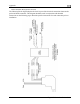
installation are pins 13 and 21. The two wires exiting the Encoder Converter are the EFIS-TX
and the EFIS-Ground, which are green (or red) and black respectively, and 2 feet in length.
atch the altitude shown on screen when
Hg.
STEP 2: CONNECTING TO THE FLIGHTDEK-D180
Before wir
your Encoder Converter and your FlightDEK-D180 is appropriate. Add or remove wire length if
needed or desired. Customizing the wire length
and more secure.
The only pins of interest on the FlightDEK-D180 connector for the Encode
Connect these wires to the FlightDEK-D180 25-pin female harness.
Ensure that your FlightDEK-D180 is powered off. Then connect the black EFIS Ground wire to
pin 21. Then, connect the green wire to pin 13 (Serial Encoder Transmit) on the EFIS harness.