
Installation Guide Instruction Manual
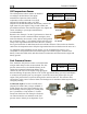

Transducer Installation
Tachometer
Dynon Avionics does not sell a tachometer transducer.
Depending upon existing equipment and engine type,
you have a few options for connecting the tachometer
inputs on the FlightDEK-D180. See the relevant
subsections below for your particular method. You may
connect different types of signals to the two different RPM inputs (e.g., p-lead to RPM Left and a
12V transducer to RPM Right). Once you have connected the tachometer inputs according to
your engine and transducer type, you must set the appropriate pulses/revolution as described on
page 6-8.
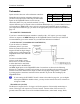
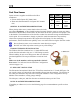
Pin Color Function
32 White/green RPM Left
33 White/blue RPM Right
TACHOMETER TRANSDUCER
If you have a standard tachometer transducer (usually with a 12V output), you may simply
connect its output to the RPM Left input on the FlightDEK-D180. Ensure that you follow all
recommendations given in the manual for your individual tachometer transducer.
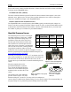
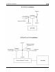
P-LEAD PICKOFF (LYCOMING AND CONTINENTAL)
If you do not have a standard
tachometer pickoff, you must
follow the instructions below. The
magneto P-lead has high voltages
which can very easily damage the
FlightDEK-D180 if not dealt with
properly.
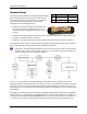
Use the two included 30kΩ
resistors (color bands: orange,
black, brown, red, brown; connect
in either direction) to attach left
and right P-leads to the RPM Left
and RPM Right inputs on the FlightDEK-D180. Connect them as shown in the following
diagram. It is important to connect each resistor as close as possible to the spot where you tap
into the P-lead. This minimizes the length of cable carrying high voltage spikes. 6 cylinder
Lycoming engines sometimes need more inline resistance to prevent false readings by the
FlightDEK-D180.
If, after setting the PULS/REV R and L values as described on page 6-8, you see higher
than expected RPM or unstable values, you may need to increase the series resistance to
as high as 150kΩ.
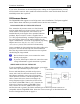
TRIGGER COIL (ROTAX)
The Rotax 912 engines have a 5
th
trigger coil for the purposes of electrically monitoring rev
counts. This trigger coil outputs to a two-wire harness. Connect either of the two wires to
ground; connect the other to one of the included 30kΩ resistors (color bands: orange, black,
3-4 FlightDEK-D180 Installation Guide