
Installation Guide Instruction Manual

Transducer Installation
brown, red, brown; connect in either direction). Connect the other end of the resistor to the RPM
Left input on the FlightDEK-D180.
ALTERNATOR WIRE (JABIRU)
The most common tachometer pickoff location for Jabiru 2200 and 3300 engines is one of the
alternator wires. Splice a wire off one of the two white alternator wires, connect it through a 1-
amp fuse to the RPM Left input on the FlightDEK-D180.
DIGITAL IGNITION AND OTHER PICKOFFS
The FlightDEK-D180 can read frequency-based RPM signals, provided the peak voltage is at
least 10 volts above ground. If the peak voltage exceeds 50 volts, use the included 30kΩ resistors
as described in the P-lead Pickoff section above. Like the other methods above, you must know
the number of pulses per revolution for your RPM transducer.
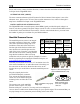
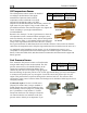
Manifold Pressure Sensor
The manifold pressure sensor is an integral
assembly consisting of three pins, a rubber
seal, and a connector housing. Strip 3/16”
insulation off the ends of the three wires
listed at right. Slide the three rubber seals
onto the three wires and the pins onto the
ends of the wires. Crimp the 3 provided pins
onto the ends of the wires, ensuring that the
long tabs that cradle the rubber seal wrap
around the seal (see picture at right for example). For more
details on preparing and crimping the Weather Pack pins, see
www.whiteproducts.net/faqs.shtml.
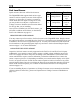
Pin
Weather
Pack Pin#
Color Function
18 C White/red
+5V
excitation
26 B Green/red
Manifold
pressure
17 A Black Ground
FlightDEK-D180 Installation Guide 3-5
Note that you will need access to the +5V excitation circuit for
other sensor installations, so make allowances for breaking out
the connection to other areas. Route the three wires to the
location where you would like to mount the manifold pressure
sensor.
C
B A
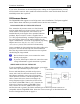
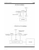
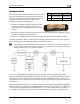
Plug the crimped pins into the
provided Weatherpack connector.
Now, mount the manifold pressure
sensor in a secure fashion using the
mounting holes on either side of the
sensor.
The pressure port on the manifold
pressure sensor requires 1/4” inner
diameter tubing for a secure fit. You may need to use adapters to
convert down to smaller inner diameter tubing for your specific engine. We recommend that you
use pipe clamps at every transition point, including at the sensor itself.
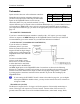
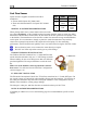
Figure 1 Connection diagram for
sensor with all black wires only
C
B A
Figure 2: Pin insertion
(rear) view of supplied
connector.
Figure 3: Detail view of properl
y
crimped pin.