
Installation Guide Instruction Manual

Transducer Installation
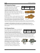
Oil Temperature Sensor
The oil temperature sensor needs to be installed
according to the directions of the engine
manufacturer. Dynon Avionics sells oil
temperature sensors with both 5/8-18 UNF
(Dynon P/N 100409-001) and 1/8-27 NPT
(Dynon P/N 100409-000) threads. Ensure that you have the
right sensor for your engine. Using a crush washer (not
provided) between the sensor and the engine case, tighten the
sensor according to your engine manufacturer’s
recommendations.
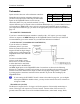
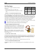
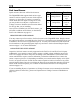
Pin Color Function
7 White/brown
Oil
Temperature
1/8-27 NPT
5/8-18 UNF
Route the wire from pin 7 on the 37-pin harness to where the
oil temperature sensor is mounted. When routing the wires,
make sure that they are secured, so they will not shift position
due to vibration. Strip ¼” of insulation off the end of the w
Crimp a #10 ring terminal onto the end of the wire, ensuri
that a good connection is made between the wire and the connector. Unscrew the nut from the
stud on the oil temperature sensor. Slip the ring terminal onto the stud and secure the nut over i
As mentione
ire.
ng
t.
d in the Grounding section on page 2-2, the oil temperature sensor is very
d
Fuel Pressure Sensor
nsor to a fixed location
riate
pe thread fitting; you may need adapters
r an
: Use the 0-30 PSI sensor
he
susceptible to voltage differences between the en
gine case and the negative terminal of the
battery. Ensure that solid, thick, and short electrical connections exist between the engine an
battery ground.
FlightDEK-D180 Installation Guide 3-7
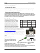
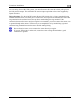
First, mount the fuel pressure se
using an Adel clamp or other secure method. The fuel
pressure sensor must not be installed directly to the
engine due to potential vibration problems. Next,
connect the fuel sensor to the engine using approp
hoses and fittings. Its pressure port has a 1/8-27 NPT pi
to connect to the pressure port on your engine. Locate the correct fuel pressure port for your
engine. This port must have a pressure fitting with a restrictor hole in it. This restrictor hole
ensures that, in the event of a sensor failure, fuel leakage rate is minimized, allowing time fo
emergency landing.
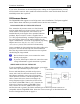
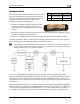
Carbureted engines
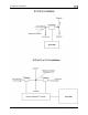
Pin Color Function
8 Brown
Fuel
Pressure
(Dynon P/N 100411-000). Crimp a standard ¼”
female Faston onto one of the ground wires (see
the Grounding section on page 2-2) coming from
the 37-pin harness. Crimp another ¼” fe
male
Faston onto the brown wire from pin 8. Push t
two Fastons onto the two terminals on the fuel
pressure sensor. Polarity is not important. If you
1/8-27 NPT
1/8-27 NPT
0-30 PSI
0-80 PSI