
Installation Guide Instruction Manual
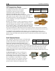

Transducer Installation
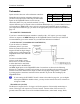
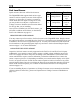
Ammeter Shunt
Pin Color Function
24 Orange/green amps high
25 Orange/purple amps low
The ammeter shunt should be mounted so that the metal
part of the shunt cannot touch any part of the aircraft.
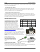
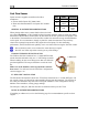
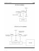
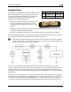
The ammeter shunt can be installed in your electrical
system in one of three locations as shown in the
(simplified) electrical diagram below.
Position A: Ammeter indicates current flow into
or out of your battery. In this position, it will
show both positive and negative currents. (-60A
to 60A)
Position B: Ammeter indicates only the positive currents flowing from the alternator to both
the battery and aircraft loads. (0A-60A)
Position C: Ammeter indicates the current flowing only into the aircraft loads. (0A-60A)
Note that the ammeter shunt is not designed for the high current required by the starter and must
not be installed in the electrical path between the battery and starter.
Electrically, the shunt should be placed so that it does not receive power when the master
switch is off. If it does receive power in this case, it is possible for your aircraft battery to
slowly discharge over a few weeks or months.
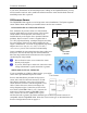
Use two ¼” ring terminals sized appropriately for the high-current wire gauge you will be
routing to and from the ammeter shunt. Cut the wire where you would like to install the ammeter
shunt. Strip the wire and crimp on the ring terminals. Using a Phillips screwdriver, remove the
two large screws (one on either end of the shunt), slip the ring terminals on, and screw them back
into the base.
We highly recommend that you fuse both the connections between the shunt and the FlightDEK-
D180. There are two methods for accomplishing this. You may simply connect two 1 amp fuses
in-line between the shunt and the FlightDEK-D180. Or, you may use butt splices to connect 1” to
2” sections of 26 AWG wire between the shunt and each of the Amps leads connecting to the
3-12 FlightDEK-D180 Installation Guide