
Installation Guide Instruction Manual


Transducer Installation
made between the wire and the connector (and resistor, if spliced in at that point). Unscrew the
nut from the stud on the coolant temperature sensor. Slip the ring terminal onto the stud and
secure the nut over it. Connect the other side of the 1kΩ resistor (color bands: brown, black,
black, brown, brown; connect in either direction) to the 5V Excitation Circuit, pin 18, as shown
in the diagram.
Rotax Pre-installed Coolant Temperature Sensor: Wire the coolant temperature sensor in the
same way as shown above for the Dynon-supplied sensor. Configure the Sensor Type as 4, as
shown on page 6-17.
GENERAL PURPOSE TEMPERATURE SENSOR
You may connect an OAT probe and configure it as a general purpose temperature measurement
(e.g., for cabin temperature). Refer to the Outside Air Temperature Sensor section on page 3-13
for installation information and to the General Purpose Temperature section on page 6-18 for
configuration information.
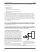
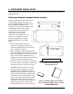
Contacts
Dynon Avionics does not sell contacts or switches.
Contacts are used for a variety of purposes, such as
monitoring canopy closure. The EMS firmware reads
the state of two contact inputs, reporting whether each
input is open (no connection to ground) or closed
(connection to ground). You may connect up to two contacts you would like to be monitored by
the FlightDEK-D180. You must ensure that when closed, the contact connects to a ground
common to the FlightDEK-D180. The voltage on the contact inputs must not exceed 15V.
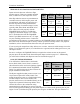
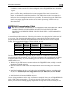
Pin Color Function
9 Brown/blue Contact 1
10 Brown/yellow Contact 2
The Contacts Configuration section on page 6-18 describes the details of configuring the
contacts, including giving them custom names.
If more than two contacts are needed, the optional HS34 includes four additional
contacts. Connection and configuration of HS34 is the same as for contacts connected
directly to the FlightDEK-D180.
3-18 FlightDEK-D180 Installation Guide