
Installation Guide Instruction Manual


Instrument Installation
4-2 FlightDEK-D180 Installation Guide
if available, to make sure the EDC-D10A is aligned with the FlightDEK-D180 to better than
1 degree.
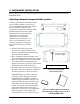
All mounting hardware needs to be made from non-ferrous material such as aluminum,
plastic, or brass. Many stainless steel screws are magnetic. If the item is attracted to a
magnet, it should not be used in the installation. The EDC-D10A needs to be mounted in a
location as free from magnetic interference as possible. This means keeping the EDC-D10A
away from any ferrous nuts, bolts, and screws, aircraft tubing, as well as from wires or
devices carrying any appreciable current such as strobe light wiring, autopilot servos, or
other electronics.
EDC-D10A Communication Cable
DO NOT ATTEMPT TO POWER UP THE FlightDEK-D180 WITH THE EDC CABLE
LEADS EXPOSED (UNSHEATHED) AND NOT INSTALLED IN THE DB9
CONNECTOR. SHORTING THESE CONNECTIONS WILL CAUSE DAMAGE TO
THE UNIT.
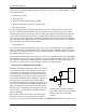
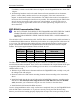
Like the RS-232 PC Communication cable, the EDC-D10A communications cable terminates in
a standard female DB9 connector. While they look similar, do not plug the EDC cable into a PC
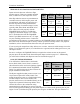
or vice versa. The following table outlines the four connections that must be made to ensure
proper communication between the FlightDEK-D180 and the EDC-D10A remote compass
module. The Dynon-supplied harness colors are listed, as well.
EFIS
DB25 pin#
EDC
DB9 pin# Function Wire color
11 5 EDC Data B White/Orange (or Red)
12 6 EDC Power White/Blue (or Black)
23 9 EDC Data A White/Green (or Green)
24 1 EDC Ground White
The EDC cable in the harness supplied by Dynon consists of 4 conductors, surrounded by a
metal shield and white insulation. These 4 wires are terminated with crimped female D-sub pins
wrapped in plastic tubing. If you are building your own cable, we recommend that you use
shielded cable as well.
With the 25-pin EFIS harness disconnected from the FlightDEK-D180, carefully cut or pull
the tubing off the 4 D-sub pins.
Route the cable to the EDC-D10A mounting location chosen according to the instructions
above.
Install the female pins in the correct holes on the included DB9 connector, according to the
chart above. Note that Dynon has shipped harnesses with different colors for the EDC
cable; determine your connections using the two sets of colors in the table above.
Install the back shell around the DB9 connector.
Correct wiring installation can be easily verified once completed. Power on the FlightDEK-D180
with the EDC-D10A connected to it. If you have correctly wired your EDC-D10A wiring
harness you will see the heading properly displayed at the top of the screen (provided you have