
Installation Guide Instruction Manual


Instrument Installation
an SL30 connected, you are able to display an HSI on either product; with a GPS connected, you
are able to display EMS fuel economy displays.
If you have a GPS and an SL30, connect the GPS to pin 19 on the EMS DB37 connector.
Connect the SL30 to pin 22 on the EFIS DB25 connector. This will allow you to flip between
GPS and SL30 inputs. You can use either the SL30 or GPS as the NAV source on the EFIS
product. You will need to disconnect the SL30 from the EFIS when doing software updates.
IF YOU OWN ONLY A FLIGHTDEK-D180
Connect the SL30 unit to pin 22 on the EFIS DB25 connector, and the GPS to pin 19 on the
EMS DB37 connector. You can display either source on the HSI using the softkeys. You will
need to disconnect the SL30 from the EFIS when doing software updates.
IF YOU OWN A FLIGHTDEK-D180 AND AN EFIS
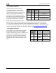
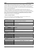
EFIS
DB25
pin#
Wire
color Function
13
Blue/White
(or black)
Encoder
serial
transmit
21 White Ground
Connect the SL30 unit to pin 22 on the FlightDEK’s EFIS
connector (vertical DB25) and the GPS to pin 19 on the
EMS DB37 connector. You can display either source on
the HSI, and you can display either on the standalone EFIS
as well (provided you have connected the DSAB A & B
lines from the FlightDEK-D180 to the standalone EFIS
product). You will need to disconnect the SL30 from the
FlightDEK-D180 when doing software updates.
Do not connect any serial devices to the secondary EFIS
device. It will only display data from the serial devices connected to the master FlightDEK-
D180.
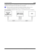
Altitude Encoder Wiring
4-8 FlightDEK-D180 Installation Guide
If your transponder requires parallel Gray
code input, and you wish to use the
FlightDEK-D180 as your altitude encoder,
you will need to purchase Dynon Avionics’
Encoder Serial-to-Parallel Converter. Please
refer to page 9-32 for more information on
the installation of this option.
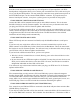
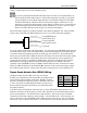
The FlightDEK-D180 outputs its altitude
measurements in one of four standard serial
outputs and is readable by many modern
transponders. The FlightDEK-D180 will
function properly whether or not this
altitude encoder functionality is used. To
use the FlightDEK-D180‘s altitude encoder
functionality, simply wire the 2 encoder
connections (GND and Encoder Transmit) from the DB25 connector to their respective
connections on your transponder.
Per ATC/FAA requirements, the serial encoder output of the FlightDEK-D180 reports pressure
altitude, which, by definition, is indicated altitude when the baro is set to 29.92. So, when you set
your FlightDEK-D180‘s baro adjustment to 29.92, its indicated altitude will match the altitude
that is being reported to your transponder.
There are four different serial formats used by transponders. The FlightDEK-D180 can output
any of these formats. To select which format the FlightDEK-D180 sends out its serial encoder
output port, you must choose the appropriate format via the menu system. When the menu