
Installation Guide Instruction Manual


Instrument Installation
outputs, connect only its wire to the variable resistor.
If you have purchased and installed an HS34 and/or an AP74, we recommend that you
only connect the HS34 audio output or AP74 audio output (but not both) to your audio
panel. The HS34 or AP74 audio output provides voice and tone outputs for both EMS-
and EFIS-related alerts. When the HS34 or AP74 audio output is connected, it is not
necessary to connect the audio outputs of other Dynon Avionics devices. Connecting the
HS34 audio output and the AP74 audio output in parallel will result in distorted audio.
Refer to the HS34 Wiring section on page 9-10 for more information.
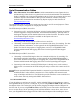
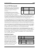
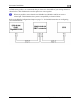
Ensure that audio outputs are connected similar to the following diagram. The 10 kΩ variable
resistor can be obtained from Radio Shack (P/N 271-1715) or other electronics suppliers.
To FlightDEK-D180
Audio Alert(s) Out
Outside terminal
Center terminal
To intercom/audio
panel auxiliary input.
Outside term
inal
To ground
To set the volume of the AOA and engine alarms, you will need your FlightDEK-D180 powered
on and the alarm output wired as described above. Enter the EFIS menu by pressing any button
(except the leftmost or rightmost) beneath an EFIS page. Press SETUP > AOAALM. In that
menu, press the TEST button. While the button is held down, the AOA alarm will sound. Adjust
the variable resistor until the volume in the intercom or audio panel is at an acceptable level.
Verify that this volume is acceptable for EMS alarms, which have a different tone. Enter the
EMS menu by pressing any button beneath an EMS main page. Press MORE > SETUP >
GLOBAL. Press DOWN▼ to select ALARM CONFIG and press SEL. Scroll down to select
TEST ALARM AUDIO. Press and hold SEL► to generate a tone on the audio output. Adjust
the variable resistor until the volume in the intercom or audio panel is at an acceptable level.
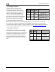
Dynon Smart Avionics Bus (DSAB) Wiring
The Dynon Smart Avionics Bus is the only way Dynon
products can communicate with one another, providing features
such as data sharing and alarm notification. DSAB is a multi-
drop bus, meaning several devices can be connected to the same
2 wires. If you have an EMS and EFIS product connected via
their serial ports through a null modem, you should disconnect
this legacy interface.
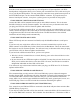
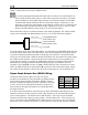
EFIS
DB25
pin#
Function
Wire
color
4 DSAB-A Green
5 DSAB-B Blue
You must connect the DSAB A connection (pin 4) on the EFIS DB25 female harness to the
DSAB A connection for the next device in the chain. Do likewise for the DSAB B connection
(pin 5). Some products – like the EFIS series and the HS34 – have only one pair of DSAB
connections on the back connector; other products – like the EMS series – have two pairs, for
wiring convenience. The FlightDEK-D180’s EMS connector does not have any active DSAB
lines on its 37-pin connector. If you have 3 or more devices in your system, and one of them is
FlightDEK-D180 Installation Guide 4-11