
Installation Guide Instruction Manual


5. EFIS CALIBRATION AND CONFIGURATION
During manufacture, your FlightDEK-D180 underwent a comprehensive calibration,
verification, and burn-in routine that minimizes setup time and ensures that your EFIS meets
Dynon’s stringent performance specifications. To account for your individual preferences and
your aircraft’s particular setup, there are a few simple calibration and configuration steps that
you must complete before using your FlightDEK-D180. This section takes you through these
steps to make sure that you have properly installed and configured your FlightDEK-D180.
CAUTION: It is your responsibility to fly your plane safely while performing any
configuration or calibration in flight. The best scenario would include a second person to
perform any necessary steps on the unit.
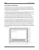
Ensuring Proper Installation
Turn your unit on by energizing the aircraft power to which it is connected. Ensure that the
screen is bright and readable and that all instrument displays appear. If a desired display item is
not present, refer to the User’s Guide to use the CLUTTR feature to display the missing item.
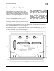
Setting Zero Pitch (In flight)
For the purposes of this setting, level is defined as the attitude at which the aircraft’s
longitudinal axis is parallel to the ground. For most aircraft, the attitude the aircraft
assumes at normal cruise speeds will be acceptable. Additionally, this feature should not
be used to “zero out” pitch when the aircraft is at an attitude other than level. Do not
think of this adjustment as you would the parallax adjustment on a normal attitude
indicator. Instead, think of it as a calibration step which is not changed often.
With your aircraft flying straight and level, enter the EFIS > SETUP > PITCH menu. Press INC
or DEC until the horizon line intersects the center of the crosshairs. It is important that this be
done while the aircraft is level to ensure proper pitch and roll display throughout all maneuvers.
Compass Heading Calibration
This section guides you through the calibration and configuration of your magnetic heading
indication. Prior to calibrating your EDC-D10A, you must configure the local magnetic
inclination and magnetic intensity as described in the sections below.
In a DSAB network, the Bus Master’s heading is used as the only heading source for all
connected instruments. However, in the event of a DSAB failure, EFIS instruments revert
to their local heading source. In a system already using a shared heading, you may still
configure and calibrate the local heading source. As soon as you bring up any of the
magnetic calibration menus (MAGINC, MAGCAL, MAGADJ, MAGINT), the heading
and DG displays switch to display the locally-derived heading indication. The display
stays on that source until exiting the magnetic configuration menu. If you do not have an
EDC-D10A connected, REMOTE COMPASS NOT DETECTED is displayed when in
any of these menus.
FlightDEK-D180 Installation Guide 5-1