
Installation Guide Instruction Manual


EMS Configuration
for each function. The various supported sensors and their types are described below, starting at
page 6-8.
Alarm and Color Threshold Configuration
In the various sensor setup menus, you will be configuring the alarms and color thresholds.
Below is an introduction to the principles used.
If you have configured EMS > GLOBAL > ENGINE TYPE to ROTAX, then the color thresholds
for the Tachometer and Oil Temperature are automatically set in accordance with manufacturer
specifications.
Alarms for any given sensor can have three different modes of operation. They are:
OFF – When the selected sensor enters the red portion of its analog gauge, no alarm will be
sounded. Use this mode if you have not installed the selected sensor or do not wish to be alerted
when its value is beyond the norm.
SELF-CLEAR – When an alarm
condition occurs for the selected
sensor, an alarm will be displayed
(and sounded, if the audio alert
connection to the intercom is
made). If the given parameter
enters normal values (i.e., comes
out of the red), the alarm will be
cancelled.
LATCHING – The alarm will
continue to be displayed, even if
the condition has returned to
normal values again.
AOA (appears only on EMS Contact 1 and EMS Contact 2) – When EMS Contact 1 or EMS
Contact 2 is activated, the AOA alarm in the EFIS section of the instrument is triggered; the
resulting alarm depends on how the EFIS AOA alarm is configured (EFIS TONE, EXT TONE,
or EXT VOICE).
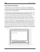
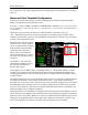
All displayed analog bars have color thresholds which must be set. Navigate to each threshold to
increment or decrement it. Each number represents the value – in the units of the displayed
parameter. So, in the picture above, the top section of the oil pressure analog bar is set to 99 PSI;
the threshold between the upper portion of red and the upper portion of yellow is set to 95 PSI;
and so on. If an alarm for a given sensor is enabled (either SELF-CLEAR or LATCHING), the
alarm will trigger at the red/yellow boundaries.
Some sensors have color thresholds on the high and low side; others have thresholds on only one
side or the other. This depends on the individual value being displayed and whether its being too
high or too low is noteworthy. Whenever a value is in normal operating conditions (green on the
analog bar), its displayed numeric value will be white. When any value enters a yellow or red
zone on its analog bar, the respective numeric value will change colors accordingly.
6-2 FlightDEK-D180 Installation Guide