
Installation Guide Instruction Manual
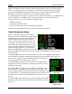


EMS Configuration
Use the DOWN▼ or UP▲ buttons to select the tank that you wish to calibrate, and press
SEL►.
Enter the approximate number of gallons or liters the tank can hold. It is not necessary to be
precise. This number is only used to determine reasonable fuel addition increments in the next
steps. Press NEXT. Once you have confirmed that the tank you are calibrating is empty, press
START. Follow the on-screen instructions until the completion of your fuel calibration.
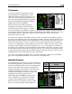
At the completion of your fuel level calibration, the FlightDEK-D180 will present you with a
table of values in the format “[pour #]: [mV] [gallons]”. Ensure that the mV values (just after the
colon) change throughout the range of pours. Also, it is highly advised that you create a backup
of your FlightDEK-D180 via the Dynon Product Support Program as soon as possible. This will
ensure that the fuel calibration data is backed up, reducing the likelihood that you’ll need to
repeat the process. Refer to the Dynon Product Support Program help file for more details on this
process. Keep the firmware backup file in a place on your computer where you can easily find it
again.
In addition to calibrating your fuel tanks, you may make a few settings that will enhance the
functionality of the fuel computer. First, entering the FULL VALUE menu will allow you to
configure the total amount of fuel available between all your tanks. This is used to calculate fuel
remaining and other values, as well as allowing you to reset the fuel computer to a full fuel value
with one button press. Likewise, the PRESET VALUE menu allows you configure a preset total
fuel value – distinct from the full value – which you can reset the fuel computer to. Finally, the
ADD THRESHOLD menu allows you to configure the fuel computer to automatically detect the
addition of fuel when the EMS was off. The fuel computer will check the fuel level senders at
boot and prompt the pilot to add fuel when it measures an increase beyond the set threshold. The
threshold is set as a percentage of the full measurable amount of fuel.
Trim Calibration
Prior to calibrating your trim sensors, ensure that you have connected them as
described on page 3-16 and made the correct trim type selection for the desired GP
inputs as described on page 6-17.
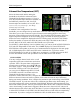
Enter the EMS menu by pressing any button below an EMS main page and
pressing MORE > SETUP > MORE > TRIM. The TRIM CALIBRATION menu
shows AILERON, ELEVATOR, and RUDDER, followed by the GP input that
each is configured as (or NONE, if no GP input is configured for a given axis).
Ensure that this list corresponds to the physical connections made during the setup
described in the Trim and Flaps Position Potentiometers section on page 3-16.
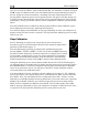
During the calibration process, the onscreen instructions will direct you to put the trim into
various positions, pressing NEXT after each change. The calibration process allows you to set a
takeoff trim position; this position is displayed as a green line on the trim scale info item. During
the calibration process, ensure that the number shown in the VALUE field changes as you adjust
the trim. If the number does not change, the trim sensor may be incorrectly wired to the
FlightDEK-D180, or incorrectly configured in the GP input selection under the SENSOR menu.
At any point in the process, you may press CANCEL to end the calibration without overwriting
the previous calibration results.
6-6 FlightDEK-D180 Installation Guide