
Installation Guide Instruction Manual


EMS Configuration
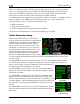
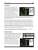
Tachometer
If you have connected a tachometer source to
either the RPM Left or Right inputs, set the
DISPLAY parameter to ON, otherwise, set it to
OFF. Next, select whether the tachometer is to
the left or right of the manifold pressure display.
Simply select POSITION and press SEL► to
toggle between LEFT and RIGHT.
Select the alarm mode and the analog bar
thresholds as described in Alarm and Color
Threshold Configuration on page 6-2. Unlike
most sensor displays, the tachometer supports a yellow band in the middle of the green band to
accommodate engines which have a range of unsafe RPMs in the middle of the safe range. If you
do not require this extra yellow band, simply set the LO GRN/YEL and LO YEL/GRN
parameters to the same value.
Increment or decrement the PULS/REV R and L values to correspond to the number of pulses
put out by your tachometer source for each engine revolution. You may select the pulses/rev for
both the left and right tachometer inputs independently. If they are both p-lead inputs, these will
likely be the same number. However, if you have connected two different types of tachometer
sources, you will likely have to input different values into these fields. If you are using a p-lead
connection, the PULS/REV value will typically be set to ½ or ¼ of the number of cylinders in
the engine. If you find that the onscreen tachometer reads double or half what you expect, adjust
the PULS/REV value until you observe the expected value. If you do not have anything hooked
to one of the tachometer inputs, the PULS/REV setting for this input can be set to any value. The
FlightDEK-D180 will automatically ignore this unused input.
Next, enter your normal cruise RPM. This is used when computing Tach Time on the TIMES
page. See the FlightDEK-D180 Pilot’s User Guide for more information.
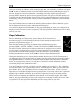
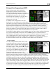
Manifold Pressure
If the manifold pressure transducer has been installed, set
the DISPLAY parameter to ON, otherwise, set it to OFF.
Change the SENSOR TYPE to the correct number using
the sensor type table. Select the alarm mode and the
analog bar thresholds as described in Alarm and Color
Threshold Configuration on page 6-2. Next, select
whether the tachometer is to the left or right of the
manifold pressure display. Simply select
POSITION and press SEL► to toggle between
LEFT and RIGHT. You will also see a similar
selection in the manifold pressure setup menu.
Sensor
Type
Manifold Pressure
Sensor
1 Dynon P/N 100434-000
2
GRT MAP-01 or MAP-
02
Select the sensor type using the sensor type table
below. If you select the GRT manifold pressure
6-8 FlightDEK-D180 Installation Guide