
Installation Guide Instruction Manual


EMS Configuration
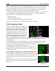
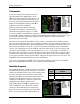
Cylinder Head Temperature (CHT)
Select the alarm mode and the analog bar
thresholds as described in Alarm and Color
Threshold Configuration on page 6-2. If one or
more CHT s
ensors have been installed, set the
DISPLAY parameter to ON; if no CHT sensors
are installed, set it to OFF. If you are using J-
type thermocouples, you are finished with the
CHT configuration; there is no need to
configure a sensor type. If you have a Rotax and
are using resistive CHT sensors, refer to the
General Purpose Inputs section on page 6-16 to configure the instrum
ent to recognize your
sensors.
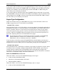
In addition to the configuration of the color thresholds, you can configure the top and bottom of
the EGT/CHT analog scales independently. This allows you to show a narrower region of
interest on the analog gauges to ensure easy detection of minor differences between cylinders.
The TOP OF SCALE parameter defines the highest temperature displayed on the EGT analog
gauge; The BOT OF SCALE parameter defines the lowest temperature displayed on the EGT
analog gauge; the SCALE SECTIONS defines the number of sections into which the entire scale
range is divided. Set the TOP OF SCALE, BOT OF SCALE, and SCALE SECTIONS to suit
your needs.
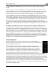
For all SPLIT cylinder displays (2 and 4 cylinders only), you can set the SCALE SECTIONS for
EGT and CHT independent of each other. For COMBD displays, EGT and CHT SCALE
SECTIONS are tied together as the two sets of measurements are displayed on the same graph.
All 1/3 EMS displays show EGTs and CHTs in the combined view. All 1/3 EMS displays show
EGTs and CHTs in the combined view. If you have set the EGT/CHT displays to be split on 2/3
EMS pages, swapping to a 1/3 EMS will cause the EGT SCALE SECTIONS value to take
precedence over the CHT SCALE SECTIONS.
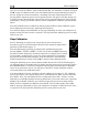
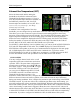
SPAN ALARMS
You may configure alarms based on the overall
temperature span between the hottest and
coolest cylinders’ CHTs. The span alarm
configuration is located on the second page;
press DOWN▼ from the bottom of page 1.
First, press SEL► to toggle the DETECT
setting to ON. Like other alarms, you can cycle
ALARM through SELF-CLEAR, LATCHING,
and OFF. See Alarm and Color Threshold
Configuration on page 6-2 for definitions of
those functions. Next, configure the MAX SPAN (the m
aximum temperature difference between
hottest and coolest cylinders, in the units shown at the top of the menu) during non-leaning
conditions. Next, configure the maximum span while leaning in the WHEN LEANING section.
If you do not wish to have a different span alarm value while leaning, you must still configure
this value to equal that of MAX SPAN. When the difference between your hottest and coldest
FlightDEK-D180 Installation Guide 6-11