
Installation Guide Instruction Manual


EMS Configuration
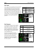
Fuel Level
If one or more fuel level transducers have been installed,
set the DISPLAY parameter to ON; if no fuel level
sensors are installed, set it to OFF. Select the alarm
mode and the analog bar thresholds as described in
Alarm and Color Threshold Configuration on page 6-2.
You may select the on-screen names for the Tank 1 and
Tank 2 inputs. You may choose from LEFT, MAIN, and
TNK1 for Tank 1. You may choose from RIGHT, AUX,
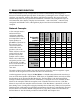
and TNK2 for Tank 2. Change the SENSOR
TYPE to the correct number using the sensor
type table.
Sensor
Type
Fuel Level Sensor
1
Resistive float-type
sender
2
Capacitive
sender(voltage output)
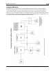
Sensor
Type
Fuel Pressure Sensor
1
Dynon P/N 100411-000
(carbureted)
2
Dynon P/N 100411-001
(injected)
3
GRT LPS-02 (remove the
external pull-up resistor)
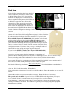
Fuel Pressure
If a fuel pressure transducer has been installed,
set the DISPLAY parameter to either TEXT or
DIAL. When set to TEXT, the fuel pressure
indication is displayed as a numerical value
above a graphical fuel flow dial. When set to
DIAL, the opposite is true. Note that changing
this value toggles the equivalent value in the
FUEL PRESSURE menu.
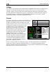
If the fuel pressure transducer has been
installed, set the DISPLAY parameter to ON,
otherwise, set it to OFF. Select the alarm
mode and the analog bar thresholds as
described in Alarm and Color Threshold
Configuration on page 6-2. Change the
SENSOR TYPE to the correct number using
the sensor type table.
FlightDEK-D180 Installation Guide 6-13