
Installation Guide Instruction Manual


EMS Configuration
GENERAL PURPOSE TEMPERATURE
6-18 FlightDEK-D180 Installation Guide
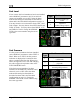
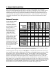
Under the desired GP input number, set FUNCT to GP
TEMP. Select the analog bar thresholds as described in
the Alarm and Color Threshold Configuration section on
page 6-2. Set the SENSOR TYPE to the correct number
using the sensor type table.
Press DOW
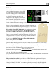
N▼ to select the LABEL 1 field. The first
character of the 4-character name is highlighted. Press
INC+ or DEC- to cycle through the numbers and letters
for the first character. When you have selected the
desired letter, press SEL► to move to the next character.
Repeat this for each of the characters in the contact name
field. If desired, repeat this for LABEL 2. If you leave LABEL 2 with its default “----” value, the
temperature units are displayed beneath the temperature bar’s label; otherwise, the value of
LABEL 2 is displayed.
Sensor
Type
GP Temp Sensor
1
Dynon P/N 100433-000
(2-wire)
Dynon P/N 100433-001
(3-wire, when installed
as described on page 3-
13)
2 GRT OAT-01
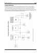
Contacts
Note that while contacts are shown below the HS34 INPUTS section, they are not available until
you purchase and connect an HS34 expansion module. Ensure you are configuring in either of
the two EMS CONTACT menus.
To access the CONTACTS configuration page, select EMS > SETUP > SENSOR > EMS
CONTACT 1 or CONTACT 2.
Select the alarm mode as described in the Alarm and Color Threshold Configuration section on
page 6-2. Contacts can only be configured as an INFO ITEM. Configure the contacts info item
to
display in the desired location(s), as described in the FlightDEK-D180 Pilot’s User Guide >
Global Configuration Settings > Info Item Configuration
section.
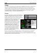
Press DOWN▼ to select the NAME field that you want to appear for CONTACT (1 or 2). The
first character of the 4-character name is highlighted. Press INC+ or DEC- to cycle through the
numbers and letters for the first character. When you have selected the desired letter, press
SEL► to move to the next character. Repeat this for each of the characters in the contact name
field.
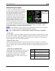
Press DOWN▼ to select CLSD LABEL. The label you enter here will be shown
when CONTACT (1 or 2) is closed (connected to ground). Select CLSD COLOR
and press SEL► until the desired color for a closed contact is displayed. Repeat
these two steps for OPEN LABEL (label shown when contact is disconnected from
ground) and OPEN COLOR.
Contact alarm triggering is based on the colo
r selected in the COLOR field for either
of the states. If you have selected a SELF-CLEAR or LATCHING alarm for a
contact and it enters a state selected to be RED, the EMS will display the alarm bar
and the contact label will blink onscreen.
The Contact Inputs listed below the HS34 INPUTS section, (HS34 CONTACT 1, 2, 3, 4)
can only be used with an HS34 installed and configured.