
Installation Guide Instruction Manual


Autopilot Installation and Configuration
8-4 FlightDEK-D180 Installation Guide
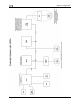
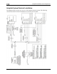
SERVO ELECTRICAL INSTALLATION
Dynon Avionics’ servos are supplied with 7 un-terminated wires, each about 8” in length. It is
the responsibility of the installer to decide on connectors and associated wiring. The 7 wires have
the following colors and functions:
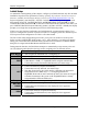
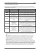
Color Function Notes
Red
Power 10-30 volts DC. Each servo draws up to 2 amps
Black
Aircraft Ground Each servo draws up to 2 amps
Green
Dynon Smart Avionics
Bus [DSAB] “A”
Connected in parallel with other DSAB devices
(Green wire on all Dynon-supplied wiring harnesses)
Blue
Dynon Smart Avionics
Bus [DSAB] “B”
Connected in parallel with other DSAB devices
(Blue wire on all Dynon-supplied wiring harnesses)
Yellow
AP Disengage/Control
Wheel Steering (CWS)
Button
Connected through a normally-open pushbutton
switch to Ground (disengages AP when button is
pushed). If two servos are installed, the yellow wire
from each servo is connected in parallel to a single
pushbutton.
White/Green
Reserved for
compatibility with
Dynon “Next
Generation” products
DO NOT CUT! During servo installation, Dynon
recommends that this be routed to the cockpit panel
(include sufficient slack behind the panel) if you
want to preserve compatibility of the servo with
Dynon’s “Next Generation” technology. This wire is
not used with the FlightDEK-D180.
White/Blue
Reserved for
compatibility with
Dynon “Next
Generation” products
DO NOT CUT! During servo installation, Dynon
recommends that this be routed to the cockpit panel
(include sufficient slack behind the panel) if you
want to preserve compatibility of the servo with
Dynon’s “Next Generation” technology. This wire is
not used with the FlightDEK-D180.
Circuit Breaker/Switch: We recommend that electrical power for the all servos be protected
with an appropriately sized circuit breaker or switch that is accessible to the pilot while in
flight.
Wire Sizing: While it is beyond the scope of this installation guide to advise on specific
types of wiring for a particular aircraft, choice of wiring should be sized to 1) minimize
voltage drop over the length of the particular wiring run, and 2) conduct the amount of
current required by the subsystem without the wiring becoming warm to the touch.
Wiring Installation: Care should be taken such that aircraft wiring is not subjected to
chafing, excessive flexing, or connections / junctions subjected to excessive vibration which
may cause the connection/junction to fail or short-circuit. If the White/Green and White/Blue
wires are extended to the cockpit panel, leave sufficient slack behind the panel for connection
anywhere behind the panel. If the White/Green and White/Blue wires are not extended to the
cockpit panel, as with other unused wires, DO NOT CUT the wires, but rather insulate the
ends of the wires (electrical tape, heatshrink tubing), bundle, and secure the unused wire.