
Installation Guide Instruction Manual


Autopilot Installation and Configuration
AP CONTROLS ELECTRICAL INSTALLATION
Circuit Breaker/Switch Install a circuit breaker or switch in a location that is accessible to the
pilot while in flight.
AP Disengage/Control Wheel Steering Button
The AP Disengage/CWS button should be in a very accessible location, usually mounted to the
stick or yoke. This button’s primary purpose is to immediately disengage the autopilot. When
configured in the EFIS > SETUP > AP > BUTTON CONFIG menu, this button can also be used
to engage the Autopilot from an “off” status by holding the button for more than 2 seconds.
This button should be a Single Pole, Normally Open, Momentary button. Verify that two
terminals of the button are shorted when the button is pressed and open (no-connect) when the
button is released. One terminal of the button should connect to both servos’ yellow wires, and
the other should connect to ground.
While not required, you may install a 5 kΩ resistor across the AP Disengage/CWS button. When
configured in the EFIS > SETUP > AP > BUTTON CONFIG > RESISTOR INST menu, the
EFIS monitors the disengage line and displays a warning when a broken connection is detected.
AP74 ELECTRICAL INSTALLATION
When installing the AP74, we recommend building enough slack wiring into the D25
connector to allow the AP74 to be removed from its tray with the connector attached.
Use the D-sub pins/connector kit included with your AP74 to make the following connections:
Pin 3: Dynon Smart Avionics Bus (DSAB) “A”, connected in parallel with all other DSAB B
connections (Blue wire on Dynon-supplied wiring harnesses)
Pin 4: Power, 10 - 30 volts DC
Pin 16: Dynon Smart Avionics Bus (DSAB) “B”, connected in parallel with all other DSAB
A connections (Green wire on Dynon-supplied wiring harnesses)
Pin 17: Aircraft Ground
Pin 25: Outer terminal of AP Audio Adjustment Potentiometer (detailed below); If HS34
installed and providing audio to your intercom system, do not connect the AP74 audio out. If
both the HS34 and AP74 Voice/Tone outputs are connected to your intercom, audio alerts
will be distorted.
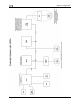
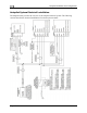
Ensure that the AP74 audio output is connected similar to the following diagram. The 10 kΩ
variable resistor can be obtained from Radio Shack (P/N 271-1715) or other electronics
suppliers. The potentiometer does not need to be pilot-accessible as it is typically adjusted only
during setup and configuration. See Step 6 - Audio Alerts Configuration on page 8-23.
To AP74 pin 5 - A
Alert Out
udio
Center ter
minal
Outside terminal
To intercom/audio
panel auxiliary input.
Outside term
inal
Aircraft ground
FlightDEK-D180 Installation Guide 8-5