
Installation Guide Instruction Manual


Autopilot Installation and Configuration
LINKAGE MOUNT POSITION FORCE AND TRAVEL
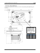
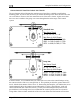
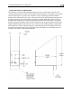
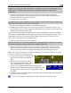
The two diagrams below illustrate the maximum travel and force available at each linkage
mounting point. As can be seen, the closer you mount the linkage to the shaft, the more force the
servo can deliver. However, this also means the travel of the arm is shorter. Again, ensure that
the servo arm is nowhere near going over-center throughout the entire range of the control
system.
FlightDEK-D180 Installation Guide 8-9
Standard Arm
Max Linear Travel
A: 2.6”, B: 2.2”, C: 1.8”
Max Force @ 100% Torque
SV32 - A: 24lb, B: 29lb, C: 36lb
SV42 - A: 36lb, B: 44lb, C: 55lb
SV52 - A: 48lb, B: 58lb, C: 72lb
Long Arm
Max Linear Travel
A: 3.4”, B: 3.0”, C: 2.6”
Max Force @ 100% Torque
SV32L - A: 18lb, B: 20lb, C: 24lb
SV42L - A: 27lb, B: 31lb, C: 36lb
SV52L - A: 36lb, B: 41lb, C: 48lb
In m
ost instances, we recommend that you connect the servo arm to the control linkages using
the outer-most hole of the servo arm (position A). This position provides the greatest amount of
travel, with the least amount of drive force. If, when testing the autopilot, you find that the servos
cannot adequately drive the control system (indicated by a yellow “slip indicator” in the AP
status at the bottom left of the EFIS screen), you may move the linkage mount point inward,
provided there is still enough travel to accommodate the control system at the servo location.
Using either of the two inner-most holes of the servo arm affects the final amount of force that