
Installation Guide Instruction Manual


Autopilot Installation and Configuration
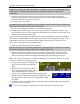
8-10 FlightDEK-D180 Installation Guide
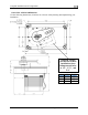
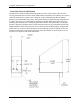
the servo can exert, arm travel, control surface resolution, and the amount of force required to
shear the brass shear screw. The two inner-most holes of the servo arm should only be used if the
installer fully understands the resulting implications. The diagrams above illustrate the linear
travel and available force for each mount point on the standard and long-arm servos.
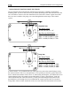
CAUTION: Each Dynon Avionics servo includes a precision-machined brass “shear
screw” that pins the servo arm to the servo arm attachment, providing an ultimate
“manual override”. The shear screw will break at the application of 100 inch-pounds of
torque, at which point the servo arm will travel freely. If the brass shear screw is broken
during AP installation or usage, do not replace it with a standard screw - contact Dynon
for a replacement shear screw.
There will be a variety of methods used to install the other end of this control linkage to the
existing mechanicals of the aircraft. Some systems will use a hole drilled into the bell crank as
the point where the servo push rod/rod end combination interfaces with the controls. Others will
use an attachment to existing linkage. Others may attach directly to the control stick itself. It is
up to the installer to decide which method is best in terms of safety and AP functionality.
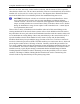
Installers should always keep in mind the range of motion of the servo. Total servo arm travel
needs to be limited to prevent an OVER CENTER condition (see caution note above), while still
preserving the control surfaces’ full range of motion. Carefully consider the prevention of an
over center condition when selecting the mounting location and linkage attachment point for any
servo installation. The built-in control stops of the aircraft will limit the servo arm travel when
installed correctly. Again, Dynon strongly recommends that the included Range of Motion
Limiting Bracket be installed in order to absolutely prevent the possibility of an over center
condition. The Range of Motion Limiting Bracket should not be used as a normal stop; the
aircraft’s built-in stops should always be the primary range limit.