
Instructions Owner manual

DYNON AVIONICS
101156-000 - Rev D Page 3 of 3
Never “re-torque” or “re-tighten” the shear screw while it is installed in the
servo. After the threadlocker has started to cure, it MUST be removed and reinstalled
with fresh threadlocker per the above instructions.
If you are experiencing several shear screw breaks contact Dynon customer service
immediately as this may be an indication of other installation issues.
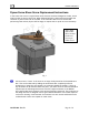
Fig 2
Reassembling the Arm/Capstan Stack
Once the threadlocker has cured, reverse the disassembly steps to install the remaining
hardware. See Figure 2. Assembly order is:
1. Servo Arm/Capstan
2. Nylon Washer
3. Wave Washer
4. Castle Nut (AN310-5)
5. Cotter Pin (MS24665-210)
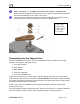
Tighten the castellated nut to finger tight, and then tighten until a slot in the nut lines up
with the hole in the shaft for the cotter pin. DO NOT EXCEED 72 in-oz (4.5 in-lb). Exceeding
this torque specification will affect the yield torque of the safety shear screw, compromising
the safety-enhancing intent of its design.
Install a new cotter pin, MS24665-210, following the standard method of trimming and
bending the pin legs.
Servo arm/capstan rotation should be smooth. After the cure period, no movement should be
observed between the arm/capstan and the attachment disc as described earlier.
1. Servo Arm
2. Flat washer
3. Wave washer
4. Castle nut
5. Cotter pin