
Service manual


Page 8
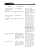
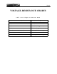
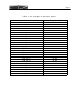
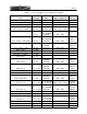
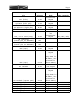
Pin Voltage Mode ModeCommands
Menu
setting
J18pin1(right) 5.0V
J5pin5(bottom) VCC
U18pin3(top) 10.0V
TestPoint:CWFM 9.5V
CWUSB,
CWLSB,FM md3;md7;md4;
9.5V
AM,USB,
LSB,DIGUSB,
DIGLSB
md5;md2;md1;
md6;md9;
TestPoint:AM‐ESSB 9.5V
AM,USB,
LSB,DIGUSB,
DIGLSB
md5;md2;md1;
ESSBon
(es1;)
md6;md9;
TestPoint:SSB 9.5V
USB,LSB,
DIGUSB,
DIGLSB
md2;md1;
ESSBoff
(es0;)
md6;md9;
JP12(top) 5.0V
JP12(bottom) 5.0V
J6pin1(left) 2.5V
JP3(top) 2.5V
JP4(top) 2.5V
USB,LSB,
DIGUSB,
DIGLSB
md2;md1;
ESSBoff
(es0;)
md6;md9;
U20pin1 2.5‐3.5V
USB,LSB,
DIGUSB,
DIGLSB
md2;md1;
ESSBoff
(es0;)md6;md9;
U20pin2 3.0V
U20pin4 2.5V
C162(bottom) 1.8V
USB,LSB,
DIGUSB,
DIGLSB
md2;md1;
ESSBoff
(es0;)md6;md9;
U17pin1 2.5‐3.5V
AsTxdrive
isvaried md3;md7;md4;
TxDrv
CW/FM
U17pin1 2.5‐3.5V
AM,USB,
LSB,DIGUSB,
DIGLSB
md5;md2;md1;
TxDrv
AM/SB
md6;md9;
U17pin2 3.0V
U17pin4 2.5V
U8pin1 2.5‐3.5V
asRFPower
isvaried
TxALC
off
U8pin2 3.0V
U8pin3 2.5V
U8pin4 2.5V
Table3.DCVoltagesonTransmitterBoard