
Service manual


INSTALLATION
2-5
Revised February 1997
Part No. 001-9750-005
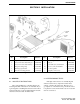
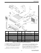
Figure 2-3 Remote Mount Installation Components
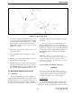
2.5 REMOTE CONTROL UNIT INSTALLATION
2.5.1 SETTING PROGRAMMING SWITCHES
The remote control unit does not require any
programming by the computer setup described in
Section 4. However, there are DIP switches on the
control unit interface board that configure the control
unit for various applications. These switches are
factory preset and should not need to be changed when
installing a remote-mount transceiver. However, if you
want to verify the position of these switches or
Item
No.
Description Part
Number
Item
No.
Description
Part
Number
1 Amplified dynamic mic 250-0740-310 8 Knob (4) 547-0016-005
2 Screw, 4-20 x 5/8” thrd frmg (3) 575-5604-020 9 Power cable (22') and hard 023-9750-010
3 Screw, 4-24 x 1/4” sheet metal (3) 575-3604-008 10 Accessory wire and hardware 023-9750-011
4 Microphone hanger clip 023-3514-001 11 5" remote speaker (optional) 250-0151-006
5 Mic hanger ground wire 023-7171-911 12 Plastic washer (2) 596-6400-015
6 Transceiver mounting bracket 017-2226-034 13 Stainless steel spring washer 596-9260-001
7 Self-drilling screw, 1.25" (4) 14 Knob (2) 032-0792-015
Transceiver 1/4” 575-9077-565 15 Control head mounting bracket 017-2226-050
Control unit #10 575-9077-545 16 Control cable (17') 597-2002-262