
Service manual


UNIVERSAL DIGITAL AND DATA INTERFACE
B-6
Revised May 1998
Part No. 001-9750-006
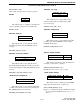
OUTPUTS
RSSI Out 21 Direct analog RSSI (Received Signal Strength Indicator) output. The DC voltage of this output
decreases from 8 - 0 volts as signal strength increases. Output impedance is greater than 100k
ohms.
AUX1 14 Active high output which is controlled by the AUX 1 option switch or menu parameter (see Sec-
tion 3.5.4). This output can be used to control an external accessory. The output levels are 0 and 8
volts DC ±10%. Maximum source current is 50 mA. Therefore, a driver circuit of some type may
be required. This output is shared with the option wire-out 8.
PTT 5 Active low output which provides the PTT signal to an external device. This output is shared with
the option wire-out 9. Programmable options are as follows. (With the Viking HT, this signal is
active high.)
Tx Sense (default) - Indicates that the transmitter is currently activated.
Standard - Indicates that the microphone PTT switch is pressed (the transmitter may or may not
be activated, depending on the current mode).
Busy Out 6 This output which provides channel/system information to an external device. Programmable
options are as follows:
Access Denied (default) - When accessing the system/channel, this output indicates a busy or
out-of-range condition. This output is active low.
RSSI - Output from the RSSI (Receive Signal Strength Indicator) circuit. This is a logic output
that reacts faster than noise squelch. Therefore, it is also subject to more falsing. Typical noise
squelch response at -116 dB is 50 ms with 6 dB of hysteresis, and typical RSSI response at this
level is 5 ms with 4 dB hysteresis. This output is active high.
Output A 15 Multi-purpose output programmable for the following functions. This is a CMOS output that can
source up to 20 mA as described in Section 6. It is shared with option wire-out 7. NOTE: When
the encryption option is installed, this option is dedicated to the Clear Code function and the
other options are not available.
Clear Code (default) - Active high output that indicates that the transmit audio signal is to be
encrypted.
Clear-to-Send - Active low output that indicates that a trunking channel has been accessed and
all overhead activities completed. This function is also programmable for Output B.
Monitor Hanger - Active low output that indicates that the microphone is on-hook (a high indi-
cates that it is off-hook). This function is also programmable for Output B.
Tx Audio Enable - Active high output that indicates that the internal transmit audio signal is
muted. This function is also programmable for Output B.
Auxiliary 2 - Same as the following Output B function.
Output B 16 Multi-purpose output programmable for the following functions. This is a CMOS output that can
source up to 20 mA as described in Section 6.
Auxiliary 2 (default) - Active high output which is controlled by the AUX2 option switch or
menu parameter (see Section 3.5.4). This output can be used to control an external accessory. The
preceding Output A parameter can also be programmed for this function.
Rx Data Group - Active low output that indicates that a call is being received on a group pro-
grammed for data signaling (see Section 3.6.11).
Clear-to-Send - Same as preceding Output A function.
Monitor Hanger - Same as preceding Output A function.
Tx Audio Enable - Same as preceding Output A function.
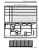
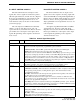
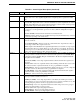
Table B-6 Control Signal Description (Continued)
Function Pin Description